

I've wanted a tower since I was 15. Albeit in sad circumstances, in 2017 (now at 52) an opportunity came up to obtain GW4BLE's tower. I hope to give it a good home.
Collection
I borrowed a trailer from G0DWV (Chris), that had been modified specifically to transport tower sections. An up-stand allows the sections to clear the vehicle and reduce the overall length, whilst welded tabs locate the rungs at the other end. Ratchet straps make for a very solid overall structure.My thanks to Rich (MW0LGE) and friends who had already got the tower sections onto the road by the time we had arrived. The photo below shows the loaded tower just before leaving for home.

After a 12-hour round trip, I and my (non-amateur) friend unloaded the sections on our own in the dark! The bottom section is very heavy and is really a minimum 3-man lift, but we were able to slide it off onto the driveway and drag it around OK.
Whilst discussing how heavy it is, Don (G3BJ) kindly gave me copies of the specification sheets for Versatowers, which I'd asked for to help specify the trailer I thought I was going to hire. I've made them available here in case they are useful to others.
- Versatower 25 spec
- Versatower 40 spec
- Versatower 40HD spec
- Versatower 60 spec
- Versatower 60HD spec
- Versatower 80HD spec
- Versatower 100HD spec
 Having now had time to inspect what I've bought, here's
a photo of the post that was cut, presumably with an angle grinder. At
the bottom, you can see that it was cut around the block that accepts
the tilt-over rode, as shown in the example photo of an 85ft trailer
mounted tower. I did have thoughts about sticking an I-beam up the post,
but this can't be done due to the tube that passes through the post
behind the luffing rope pulleys. Conversion to a baseplate mount seems
favourite.
Having now had time to inspect what I've bought, here's
a photo of the post that was cut, presumably with an angle grinder. At
the bottom, you can see that it was cut around the block that accepts
the tilt-over rode, as shown in the example photo of an 85ft trailer
mounted tower. I did have thoughts about sticking an I-beam up the post,
but this can't be done due to the tube that passes through the post
behind the luffing rope pulleys. Conversion to a baseplate mount seems
favourite.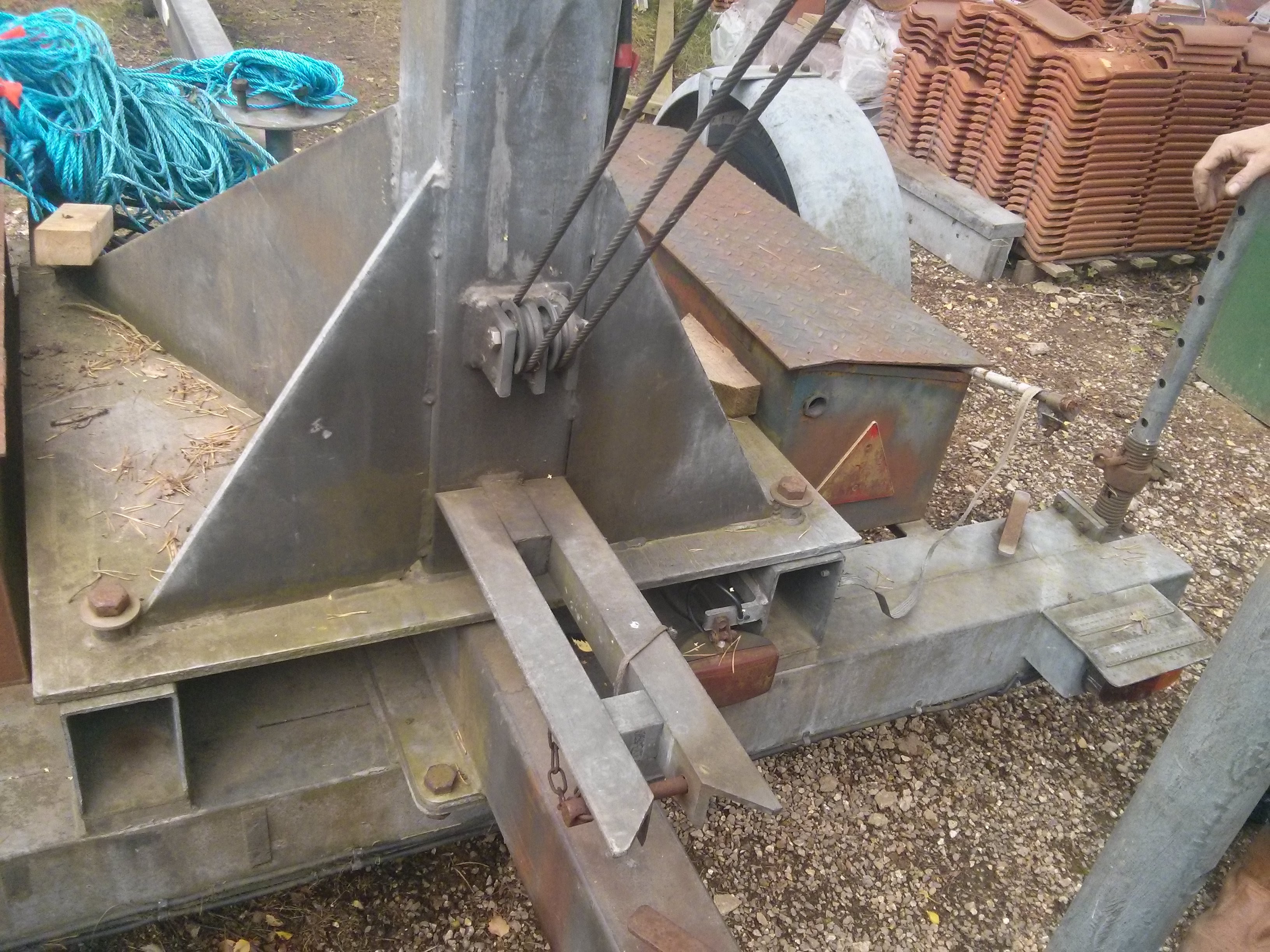
Probably the simplest thing to do is to weld plates to the four sides and then weld a block to the new face. The tilt-rode will need to be shortened slightly. Then a new baseplate will need fabricating and welding onto the bottom of the cleaned-up post.
It has been suggested to me that I might instead start with a new 12ft post, keeping it a post mount rather than turning it into a baseplate mount, and weld the ancillary parts onto that. Not sure at the moment!
Planning Permission
Over the 2017/18 Christmas/New Year break, I created some plans for the tower's location, etc. using LibreCad; a free 2D CAD application. I then went round to see my closest neighbours and explained what I wanted to do, leaving them with copies of the plans. I also used the 'Neighbour Reaction' proforma as recommended in the RSGB's Planning Permission Guide booklet. Of the four neighbours I canvassed, only one subsequently signed the form supporting my application. The others declined even to sign the objection forms. Fortunately, the neighbour who supported me was the most important to get on-side. Sadly, my other closest neighbour went into an old people's home after I had approached him and one of his sons about my tower, and after they had verbally agreed they wouldn't object. This delayed the whole proceedings, as they had more important matters to deal with than sign my form. To cut a long story short, they wanted me to move the location a bit, so it would be obscured more by a tree. I ended up submitting the application through the Planning Portal on 16th June 2018. The application can be found in the Babergh & Mid Suffolk District Council public database by going here and searching for DC/18/02773.
I solicited opinions from several other Amateurs who had successfully applied for something similar - one in the same council area. I had one suggestion to increase the height in anticipation of being negotiated down. I did do this, by increasing the stub mast height, but it went through as it was! I think the key difference here was that the Parish Council didn't object.
Once the application was available for public comment on-line, one of
my neighbours immediately objected partly on the grounds of being
'irradiated by microwave radiation', which is surprising given that
they are both doctors and should have known better. Another neighbour
objected partly on the grounds of potential interference. Both thought
it would be an eyesore.
After I applied, I contacted the RSGB to supply a letter of support. It was actually nip-n-tuck whether they would receive this before the public consultation deadline, so if I were to do this again I think I'd contact the RSGB before making the application. The application does have to be made, however, before they can send the letter, as it must reference the application. They were able to address some of the issues raised by the objecting neighbours.
In addition, I waited until the final day of the public consultation and added my own responses to some of the objections raised by the neighbours. You can find these attached to the application, but I think it's worth spelling them out here:
"In response to Dr Charles Noble-Jamieson's comments regarding 'microwave radiation' posing a health hazard, I would like to draw the Committee's attention to the latest advice given by the Government's Health Protection Agency, which may be found here:
The HPA regularly review current research on this subject. The
last time this occurred was in 2012, covered by this report. They
conclude: "In summary, although a substantial amount of research has
been conducted in this area, there is no convincing evidence that RF
field exposure below guideline levels causes health effects in
adults or children".
The proposed mast/aerial will be used for transmitting 'short
waves', not 'microwaves', as indicated in the application. In fact,
much larger doses of microwave radiation would occur from their own
microwave oven, WiFi (access point and laptops), and mobile phones.
In response to Mr Roger King's concerns over interference, I would
like to point out that there have been zero complaints of
interference during nearly 4 years of transmitting with aerials that
are much lower to the ground. In general, interference risk reduces
with the height of the aerial. Interference should therefore not be
a consideration."
Since it might help others in their application, I have made relevant documents available in the table below:
| Description | File |
| Covering letter | CoveringLetter.pdf |
| Plan view | Sheet1.pdf plan4.dxf |
| Side elevation | Sheet2.pdf side_elevation4.dxf |
| Front elevation | Sheet3.pdf front_elevation4.dxf |
| Site plan | SitePlan.pdf |
| Versatower datasheet | Versatower_data_sheet.pdf |
| Versatower BP foundation | Versatower_BP_foundation.pdf |
| Neighbour reaction form (supports) | MartinAdamsReactionForm.pdf |
| RSGB letter of support | RSGB_support_letter.pdf |
| Decision letter | ufm9.pdf |
Note that it must be standard practice not to make the covering letter available on the public database, as it was definitely sent to them. I also know this has happened with other people's applications.
As you can see, I was granted permission with no additional constraints on 17th July 2018. Hurrah! I now have 3 years to get it into the ground...
My thanks to all those who have helped me with the application. Special thanks to G3XLG, G0TSM, M0BCT, G4TEQ.
Baseplate conversion
I didn't want to tempt fate with the Planning Permission, so I hadn't done anything about converting the post to a BP version. Neither do I want to pour foundations until I have the BP in my hands. So now this work has become a priority!
The first thing I wanted to do was create some 2D CAD drawings, so I could send them to welding fabricators for quotes. Quite a few people have done this before, but there seems to be a lack of publicly available engineering drawings to work to. I am much indebted in particular to Martin (M0BCT), who had some hand-written drawings, and made several measurements of his own 6BP6 HD converted post. Also thanks to G0TSM who supplied his own hand-written drawings. With this information and that available at Chris's (GM3WOJ) tower page, I was able to create some drawings that might also be useful to others:
In the end, I decided to use MM0CUG to do the conversion, on recommendation from G0TSM. Gary collected the post at the and of August 2018, but I didn't get it back until the end of January 2019. I must say I found this quite stressful, as I had to chase him up frequently. I gather the mast business has taken off somewhat and I think I was down the priority list. However, I have to say that the welding job is superb, as evidenced by the photos below.


The entire assembly was shot blasted and re-galvanised.
I was right to wait until the post was back in my hands before pouring concrete, because Gary didn't quite stick to my drawing dimensions for distance between mounting hole centres (765mm vs. 762mm).
Hole digging
I started digging the hole at the end of October 2018. Several weekends over the next three months were consumed in this process. The Suffolk clay with seams of chalk and flint make it difficult going. A house extension was also going on at the time, which was a distraction, as well as Christmas! The photo below shows the state of play at the end of January.
I used 150 x 47mm timber to form the opening, which was initially made level in small ditches. Four off-cuts of 50mm angle steel were driven-in and screwed to the outside of the timbers to secure them. The hole was then dug by hand from within.
Each corner has a 2.4m earth rod (comprising 2x 1.2m copper plated steel extendible rods), for RF earthing purposes. Small pieces of OSB hold the tops in-place. I discovered that these earth rods have a 5/8" BSW thread, and it's possible to find brass nuts that will fit them. The plan is to bolt a brass bus-bar between them to connect radials to. An SDS drill with a suitably sized impact driver socket made light work of driving the rods in.
Holding down bolts
The recommended holding down bolt length is 450mm, but I decided to add extra margin, so went for 600mm long bolts. I got them from holdingdownbolts.com. After much consideration, I decided not to use wax cones, which allow the bolts to be 'persuaded' to move to accommodate inaccurate bolt positioning. Not using them requires you to be very accurate in positioning the bolts. To achieve this, I fabricated a positioning jig from mild steel, as can be seen in the photo below:
All the steel, including the bolts, are tack welded (using a MiG welder), so there will be no chance of movement when the concrete is poured. In addition, I offered-up a 900 x 900m piece of 11mm plywood to the bottom of the base, marked the position of the holes, and drilled their centres with a 25mm auger bit. This was used as a final confirmation that the bolts were in the correct position.
Concrete ready to pour
When I uncovered the hole, I discovered that one of the sides had caved-in a bit (the first side I had dug). I had noticed that it was bulging a bit, which I had put down to the particularly dry summer and it getting gradually wetter. I guess though that soil is actually fluid, albeit with very high viscosity, and this is a lesson to be learned regarding digging a hole over an extended period of time. Anyhow, I panicked and decided to shutter all the sides, in case things got worse, as shown in the photo below, taken at the end of February 2019:

Here, you can also see the copper straps that run across the bottom and up the sides. The idea is that this forms a Faraday cage around the concrete, which in the event of a lightning strike will encourage current to flow around the concrete, rather than through it. This is to protect the integrity of the concrete should this happen. It is not intended as an RF earth, but will be bonded to it.
The copper straps are actually made from eight 3m lengths of flattened 22mm copper pipe, soldered and bolted together (with brass nuts and bolts) to form four lengths of 6m. Believe me, flattening this much copper pipe is not for the faint of heart, but it's substantially cheaper than buying copper tape of similar dimensions.
Pouring the concrete
I decided that it was going to be too stressful to arrange the concrete and ensure enough friends were available to help, so I used the builders that were currently working on my house extension. I specified 3.47 cubic meters of concrete, which equates to about 8.33 tonnes, I also specified C35 mix, which has a higher cement content and therefore has greater compressive strength (e.g. see different-types-of-concrete-grades-and-their-uses). The pour was done on 22nd Feb 2019. There were four of us (including me), each with a barrow to bring the concrete through to the back garden from the concrete mixer on the front drive. It took a couple of hours to do this. In the photo below, you can see Phil the builder tamping the surface.

There was a bit more water in the mix than I would like, and we had to use a plasterers float to push the excess over the sides as much as possible. As the concrete started to set, I used the plasterers float to improve the finish. Towards the end of the day, it was covered with a tarpaulin and left for a couple of weeks.
Installing the post
On 17th March 2019, Graeme (G0WXI) kindly helped me to get the base post onto the concrete. I had already got the builders to move the post next to it when they were here to pour the concrete, so we only had to move it a short distance. Even so, with only two of us, we had to devise a way of shifting it onto two timbers that straddled the concrete but were proud of the bolts. The photo below shows the post in position over the well greased bolts, with wooden chocks now replacing the timbers. This allowed us to drop each corner a bit at a time.

Underneath the bottom plate, in the middle, I placed an 8mm thick, 400mm x 60mm piece of mild steel, as per Chris's (GM3WOJ) recommendation. This allows the post to pivot enough when the bolts are tightened to make the first tower section perfectly vertical. I sprayed this steel bar with zinc primer to minimize corrosion.
It was gratifying that the post went onto the bolts without any trouble, so all that effort with the bolt template had been worthwhile.
The bottom section is quite heavy and two people can't easily lift it above head height at the same time as dragging it along, so we needed a cunning plan to get it onto the post. A spare 1.8m long 125x75mm fence post was strapped to the tilt-over rode side of the post using ratchet straps, such that it provided some extra height. The another ratchet strap was attached to the pulley bolt, over the top of the fence post and onto the first lower horizontal bar of the tower section. This allowed us to get the end of the tower section resting on top of the post without too much trouble. Next, another ratchet strap was used between the pivot pin sleeve and a horizontal bar much further along. The fence post was the removed. We were now able to pull the tower section toward the post. The vertical tubes of the tower section actually run slightly to the outside of the pivot pin ends, so it doesn't fall through the gaps in the slats. All the time, the opposite end of the ground was run on planks of wood so it moved more easily. Once we got it into position, the pivot pin was greased using copper grease and pushed through. The photo below shows the state of play at this point.

When you consider that the tower section is 6.1m (20ft) long, and the pivot is at 1.8m (6ft), only 4.3m of its weight needs to be pulled to get it vertical. We were therefore able to use a ratchet strap again in lieu of a winch to get the tower section vertical. The tilt-over rode was of course fitted at this time and the securing pin fitted.
Now it was possible to check how vertical the first tower section was. Some adjustment was required, by tightening/loosening the holding down nuts. The photo below shows it in all its glory!

On 7th April 2019, I finally found time to grout the gap between the concrete base and the underside of the baseplate. To do this, I made some forms out of old lengths of 47x47mm wood to surround the baseplate, but with about 20mm gap all round. Sika Grout 212 Cementitious Grout was used, poured into this gap. This stuff is specifically made for grouting underneath machinery, stanchion plates, etc. It has high compressive strength, is shrink resistant, and best of all flows really well. Quite a bit of the stuff disappeared underneath! Once the level had settled, I was able to remove the excess so it was flush with the top of the baseplate. The photo below shows this stage, before covering up to set overnight.

Installing the winches
On 28th April 2019 I fitted the electric winches. My thanks to Andy (M0NKR) and others for advice on suitable winches.
The luffing winch (shown in the left hand photo) is a Winchmax WMSL1350012V on a WMMP2 mounting plate. The latter was cut-down to a more suitable width, drilled to match the posts attachment holes, zinc primed and painted with Hammerite. The free-spool clutch handle was removed for safety's sake. At some point, I'll hacksaw the handle off and re-fit, rather than rely on the self amalgamating tape covering the hole!
The raising winch is a Warrior Ninja 4500 (45EWHST12) from Electric Winch Shop. This is actually sold as a hoist, rather than a winch, which has the free-spool removed already. It comes with a mounting plate, which must be drilled to match the mounting holes on the bottom tower section. One of the existing holes had to be filled using a welder and then ground flat, because one of the new hole locations was too close. Again it was primed and painted. I'd say this winch is a little under-powered for the task, but I won't be putting anything big on the tower in the short term. If I had my time again, I would have bought two of the Winchmax units.
All the bolts and nuts were liberally coated in lithium grease to help prevent corrosion. I'm sure this will be a regular task!


Assembling the tower sections
Once the winches were operational, I was able to assemble the remaining tower sections. I had already gone over these (and the bottom section) to clean and repaint (using Galvafroid) any areas of suspected corrosion onset, re-paint the red height markings, and re-grease bolts and pulleys. I was able to insert the sections single-handed by dragging them along planks and adjusting the angle of the luffed-over bottom section(s) with the winch. Reaving was a fairly simple task, following the instructions on Chris's (GM3WOJ) tower webpages.
The raised tower, including rotator cage is shown below - marvelous!


Completing the earthing arrangements
On 27th May 2019, I found the time to complete the earthing arrangements. In the photo below, you can see I have now formed the copper straps that encircle the concrete foundations and bolted them to the baseplate webbing. Brass bar is used to form a busbar that bolts onto the four 8ft earth rods in the corners. It is also bolted to the copper straps. Wherever the copper is bolted, it is first tinned and cleaned to reduce the risk of corrosion adding resistance. The bolts and nuts have been covered with clear silicone sealant to further reduce the possibility of corrosion.
The idea is that I will drill and bolt (using brass nuts & bolts) the busbar as needed for radials. In fact, you can see some radials from the original vertical have survived and will eventually be bolted to it. I need a lot more than this!

Stub mast and rotator
In June 2019 I acquired an RC5A-3 rotator from Adrian, G0KOM. Apparently it had once turned the SteppIR on top of Waters & Stanton in Essex, which is no longer there.

The thrust bearing is the usual Yaesu GS-065 type. I wanted a fairly lightweight stub mast so that it could be relatively long, provided I didn't put much right at the top of it. I ended up buying a couple of 20ft aluminium scaffold poles from Actavo because it was the cheapest means of delivery. In the end, I cut the pole down to about 16ft because I thought it was too flimsy. You can get much thicker walled aluminium, but they're quite expensive. Steel scaffold poles might be an option in the future, if the head-load becomes significant.
Some antennas go up!
Also during June 2019, I managed to get some antennas up!


On top is a 5-ele Tonna for 6m. I was given that as a leaving present when I changed jobs in 1998, but has never been out of its box! It's fed using some CNT-400 (equivalent to LMR-400) that was given to me by Graeme (G0WXI). Below it is a homebrew nest of apex-up delta loops for 10/15/20m. The bottom cross-arm is fashioned from fibreglass fishing rods. This is fed via a homebrew 2:1 balun as per a W2FMI design. It's amazing how much advantage you get just from the ability to point it in the right direction!
In March 2020 I finally got the antenna switching installed at the base, as shown below:

It's a standard steel electrical enclosure, but with the back-plate replaced by brass sheet. Brass angle forms a bulkhead for female-to-female SO239 chassis sockets, and XLR connectors, which is bonded to the tower base earthing busbar. The rotator control cable goes via two of the XLR connectors, to allow decoupling of each wire to earth. The remaining XLR connector is used for control of the Top Ten Devices 6-way switch. In the long run, I'll replace this switch with an SO2R switch, but I already had the Top Ten Devices unit. Cabling is via standard 100mm BT duct.
The installation at this point enabled me to win the John Dunnington G3LZQ trophy in the 2020 RSGB Commonwealth Contest (leading UK&CD Restricted Unassisted). I had told myself that I would give that section 'a good go' before I put a proper HF beam on top. After which it wouldn't be possible to enter that section (at least not without changing back). So that worked out quite well!
Come July 2020 I finally got the HF beam I wanted. It's the TRI-12 model from Momobeam. This at least isn't an Optibeam clone, like most of its type. In fact, it has an extra 15m element, so it is 3-ele on 20m, 4-ele on 15m and 5-ele on 10m. The turning circle fits within my grounds with a couple of feet spare, but the neighbour's silver birch encroaches and means I can't rotate it when the tower is retracted. If I had put the tower where I had originally wanted to this wouldn't have been a problem, but compromise was necessary to get the planning permission.
The TRI-12 is 36kg, so I thought it would be a god idea to up-rate
the stub-mast at the same time. I did consider increasing to 2.5-inch
diameter, but in the end I stuck with 2-inch because it would have
meant different mast-to-boom clamps. I did, however, go for increased
wall thickness (2inch x 1/2-inch wall, 6082T6, 5m long, sourced from aluminiumwarehouse.co.uk).


Next thing on the list to do is to add some guying, so that I can worry a bit less!
Adding some guying points
The first thing to solve in adding guying is to add some guying points. My tower was originally sold as 'free-standing', so didn't have any guying points. In October 2020 I solved this problem, stealing some ideas from Martin (M0BCT), who has done the same thing.
It's all based on galvanised gate eyes, which you can get from any good ironmongery. Three with 12mm diameter are used without modification to replace the rotator cage fastening bolts. I would have preferred longer bolts, so that I could get a nut at either end, but they weren't long enough for that.
I then used 4" x 19mm eye bolts for the next section down and 6" x 22mm for the bottom section. These need to have the nuts ground down so that they form a snug fit inside the three tubes at the top of each tower section. To stop the end nuts working loose they were spot welded. Heavy duty M18 and M22 A2 stainless washers are used to sit the eyes proud of the tubes they sit in. Since the nuts have had their galvanising removed, I used Galvafroid, and then liberally coated them in grease. They will rust in time, but that will a very long time. It's not easy to get small items like this re-galvanised as a hobbyist. If I get the chance, I can remove them and do that at a later date.

Here's a photo of the eye bolts in position:

I intend to add D-shackles, thimbles and Mastrand guys, but that will have to wait until I get the ground stakes in.