

Let's answer this question by seeing what goes wrong when a balun isn't used.
A dipole in free-space
First consider a dipole in free space:
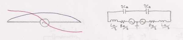
The diagram on the left shows antenna current (blue) and the antenna
voltage (red). Is this balanced? In definition of balance
we discussed how we need a reference potential with which to consider
this question. The diagram on the right shows the equivalent circuit
with the source split into two and referenced to earth potential in
the middle. The antenna can be thought of as having distributed
inductance along its length and distributed capacitance between each
half. We can simplify this by lumping all of the elements together as
shown, with Ra representing radiation resistance. At resonance only Ra
exists, but resonance is not a prerequisite. Clearly, because the two
halves are a mirror image of each other, the impedances are equal, the
voltages are equal, and so therefore must the currents be equal, which
is the condition for balance.
It's obviously not practical to have the differential source at the antenna, so let's use a balanced feedline and imagine the dipole so far off the ground it can be considered to be in free space, as in the diagram on the left below:
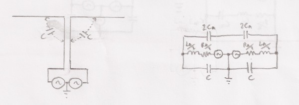
There is clearly a line of symmetry, so the capacitance from each half of the antenna to either of the feedline conductors (C) is identical. Therefore, the net voltage/current induced onto the balanced feedline by the antenna is zero. We are actually exploiting this symmetry to get power into the antenna via a route where the antenna doesn't really notice it. Alternatively, you can think of the differential source right up at the feedpoint and represent the feedline with a single wire to earth. Again, this wire cannot radiate because the currents induced by C on each side are equal and in antiphase.The equivalent circuit is shown on the right. At low heights there will also be significant capacitance between the antenna and earth, which can also be lumped in with C.
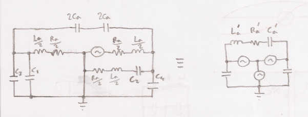
It doesn't matter whether this dipole antenna is horizontally or vertically orientated. Provided it can be considered to be in free space, and the feedline runs perpendicular for many wavelengths, it is a balanced system. When this isn't the case, and it is vertically orientated, we have the following situation:
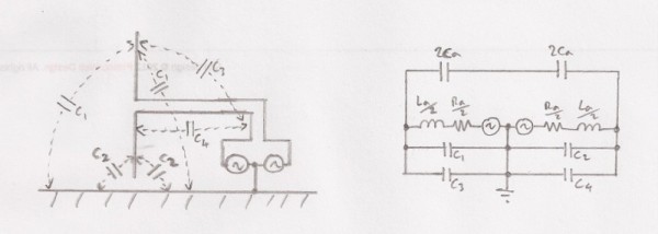
Clearly, C2 will be bigger than C1, and C4 will be bigger than C3.
Therefore, in the equivalent circuit, there are unequal impedances on
either side and the system is unbalanced. The greater the ratio of
these capacitance, the more the virtual centre-tap shifts from the
centre. In the limit, C2 & C4 become short circuits, and we
have an unbalanced antenna. This scenario effectively exists when a
ground-plane antenna is very close to earth. So in practice there are
many shades of grey between a truly balanced antenna and a truly
unbalanced antenna.
Feeding a horizontal dipole with unbalanced line
This is the classic case where it has been argued that a balun is
required. Let's take a look.
On the face of it, the two halves are balanced with respect to earth
but unfortunately, this model is too simplistic. The key here is to
understand that there can be no capacitance to the centre conductor of
the coax, and that the coax outer acts as a third wire - courtesy of
skin effect.
Let's assume the coax is 1/2-wave long. We might expect this to result in the worst case condition because it presents a low impedance path to ground. At the feedpoint on the earthy side of the antenna, C1 to the outside of the coax braid is short-circuited because they are directly connected together; it's as if C1=0. Traveling away from the feedpoint along the antenna and along the coax, C1 is still zero because the standing wave potential on the antenna and coax outer are identical. C1 looks as though it's not there because there is no voltage developed across it. Continuing down the coax, the standing wave potential falls to zero at the 1/2-wave point and may be connected to earth without upsetting the standing waves. But this clearly doesn't happen for the other half of the antenna because at the feedpoint the inner and outer of the coax are in voltage anti-phase. Thus C2 does play a part and must induce a common-mode current on the coax braid outer.
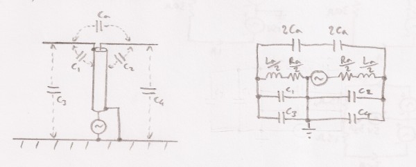
Let's re-draw the circuit including the resonant effect of the
coax outer:
A second series resonant path to earth is formed via C2 and the inductance of the coax outer to earth. As already mentioned, the circuit could be drawn without C1, as it never has any potential across it. There are now different impedances for each half of the antenna model. We know that a system with unbalanced impedances to ground can be modeled with a properly balanced differential circuit together with a common-mode circuit, which is shown on the right. We should be able to detect current flowing between the coax braid and earth at the bottom, and indeed real antennas exhibit this effect.
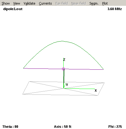
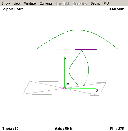
The problem can also be observed in a NEC simulator. I used 4NEC2 to obtain the following antenna current distribution of a dipole with an extra 1/2-wavelength wire connected to one side of the source at the centre, to ground:
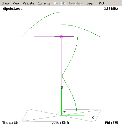
Half of the current that should be flowing in the earthy half of the
dipole actually flows in the coax braid outer.
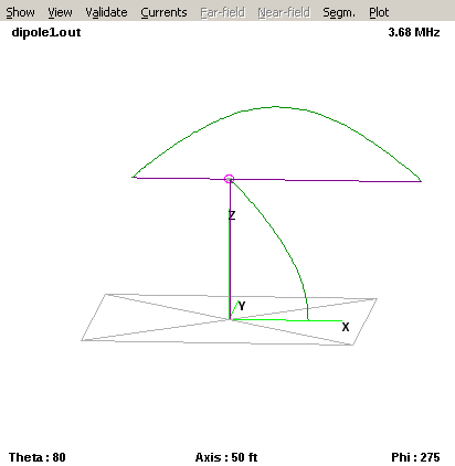
We might guess that things could be a lot better if the coax length were 1/4-wave, and it is:
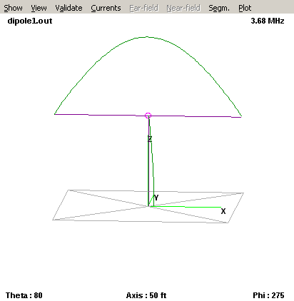
You can still detect some feedline current, but it's significantly smaller. In fact I had to tune the length of the 1/2-wavelength long feedline very accurately in order to see the worst-case effect, so it's not surprising that some people have problems whereas others don't.
The addition of a balun at the feedpoint solves any potential problem by ensuring that the antenna is excited differentially with respect to the coax braid. Provided the antenna is truly balanced, it makes no difference if this is a voltage or current balun.
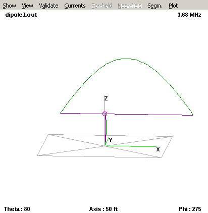
In most ham installations it's difficult to know the exact length of the wire that eventually connects to ground because there is likely to be multiple earths, explicit or otherwise. Current, or choke, baluns have the useful property of breaking the RF braid connection, which is useful in better defining the electrical length of the coax. Besides placing such a balun at the feedpoint, it should be possible to obtain the same result by placing it at any multiple of 1/2-wavelength along the coax. The plot below shows the result with 1/2-wavelength coax, but disconnected from earth:
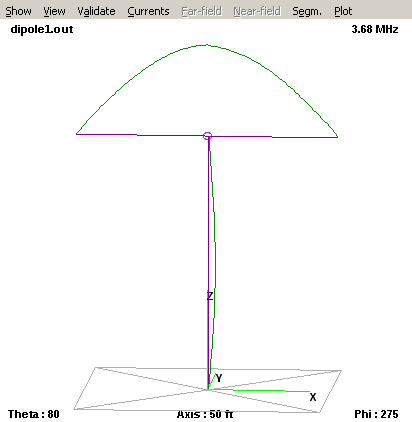
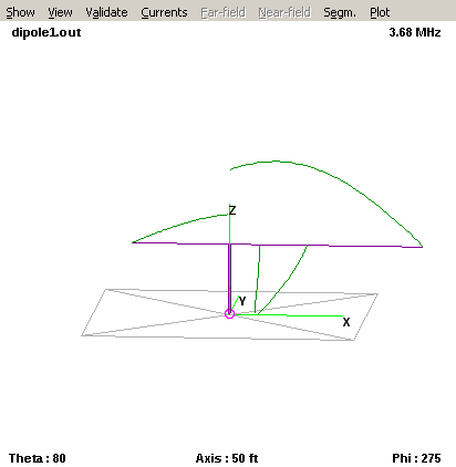
Interestingly, here's the result at 1/8-wavelength:
The result is just as good, and is of interest because it opens up the possibility of not needing to place a heavy balun at the feedpoint where said feedpoint is physically unsupported, e.g in stealth antenna situations.
Off-centre-fed (OCF) dipole
I used a Windom antenna for a number of years because a short mast was available at the house and the back garden was much longer than the front. A Windom allowed the heavier feedpoint to be located at the mast, making it possible to use stealthy lightweight wire with little sag. But I had issues with RF in the shack on some bands, and I got a lot of noise from the house wiring coupling into the antenna. At least some of this was via feeder common-mode pick-up, and was worst at LF. I tried balanced antennas off the same mast, but these were necessarily shorter overall. NEC simulations showed that the Windom should radiate better in these particular circumstances.
I've entitled this section OCF dipole because, at least on 80m, this is exactly what it is and it also represents the worst case for unbalance.
A typical OCF dipole is fed at 1/3rd of its length. Referring to
previous discussion, we know that the antenna impedance is not
balanced with respect to earth. If we simply feed this antenna with
coax we have a similar situation to the dipole, where the coax braid
outer can form part of the antenna. Alternatively, we might feed it
using a voltage balun, but again from previous analysis we know that
forcing the differential voltage to be equal results in unequal
currents in each half of the antenna. The difference appears in the
common-mode.
No problem you might say, we'll feed it with coax and use a current balun at the feedpoint, which will ensure that there isn't any common-mode current flowing in the feeder - right? Not necessarily. Consider the following NEC simulation of an OCF dipole with a grounded 1/4-wave wire simulating the feeder that is not connected to the antenna, it just gets within 10cm of it.
There is about the same current flowing in the feedline as in the antenna! This occurs because currents induced on it via capacitance to the intended antenna do not sum to zero, which would have happened if it was located at the line of symmetry. Fortunately, we can use the same trick we used with the dipole to discourage feedline currents. The plot below shows what happens with a 1/8th wavelength feedline that is disconnected at top and bottom.
Next to the mistake that I made. I thought it would be just as good to use balanced 300R twin from the feedpoint and add a 4:1 balun at ground level. Surely, if the feedline currents are forced to be equal here they would also be equal at the feedpoint? Wrong! Look at the NEC simulation below, where an 1/8-wavelength balanced feedline has been added and is driven by a current source at the bottom:
There is significant feeder radiation. The problem is that the feedline current can only be guaranteed to be equal again every 1/2-wavelength, so let's try that:
Now we have equal currents at the feedpoint, but look at the currents on the two feedline wires. Normally we would expect a balanced feedline to have a standing wave pattern such that the currents are always equal and in anti-phase (the plot shows only the magnitude). Since they are not, the feedline will radiate. The reason is that the ends of the antenna must have zero current, so the standing wave pattern must continue down the feedline as though it was part of the antenna.
An interesting article appeared in August 1990 QST titled "The
Off-Centre-Fed Dipole Revisited: A broadband, Multiband Antenna", by
VE2CV & VE3KLO. At the time of writing, this was available here.
What's mainly of interest is that the balanced feedline was made from
two 15m lengths of RG-62A 95 Ohm coax, creating 190 Ohm shielded
balanced line. There is no choice but to connect the braids to earth
at the transmitter end in order to fix the potential of the braid. The
braids are connected together again at the feedpoint but to nothing
else. The potential merit of this arrangement is that the balun need
not be located at the feedpoint.
We can certainly say that the braid outer should have the same issues associated with pick-up from the antenna wire, and that therefore odd multiples of 1/4-wavelength should be avoided. The proposed feeder length is only 1/16th-wavelength short of 1/4-wavelength on 80m, which seems a bit close for comfort.
What about the issue of unequal standing waves seen with the balanced feed arrangement? The inside of each coax braid must have the same standing wave pattern as its centre conductor, but in anti-phase. That means that the braids at the feedpoint have the same current, but are in anti-phase. Crucially, and unlike the un-screened balanced line, the two are connected together and so the currents must cancel. There is no current left to create a common-mode standing wave pattern.
In my view it is easier to define an open circuit on a coax feedline
at a specific electrical length (using a ferrite choke) than it is to
define a short circuit to ground. So I would recommend the standard
4:1 (or 6:1) current balun at the feedpoint with an additional choke
isolator located preferably before the coax reaches the ground and
avoiding electrical lengths close to multiples of 1/2-wavelength.