

It seems to me that there is a lot of confusion about what's balanced and what's unbalanced. Let's try and sort out the terminology.
Let's start with something we can all agree on: coax is an 'unbalanced' feedline, whereas 'open-wire' or 'twin' feedline is 'balanced'. But what makes them so? Consider the two scenarios below:
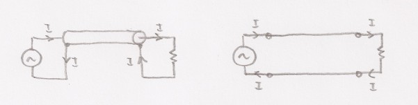
From Kirchoff's current law, all of the current that is delivered to the load must return to the source. At RF, electric potential together with skin effect causes the forward current to flow on the outside of the coax centre conductor, and return down the inside of the coax braid. Similarly, current flows on the outside of one of the balanced line conductors and returns on the outside of the other conductor, with higher current density on the inside facing surfaces due to electric potential again. The polarity reverses at the rate given by the frequency of excitation.
At any point on either type of transmission line the forward current equals the return current, even if the line is mismatched. Indeed it is this that ensures it doesn't radiate. We must therefore conclude that equal currents do not necessarily imply 'balance'. This is worth mentioning because often authors describe how 'current' baluns work by forcing equal currents. Whilst this is true, it's not necessarily an indication of a balanced system. For example, consider the following two scenarios:
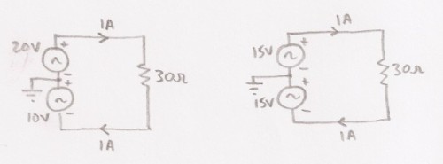
Is the circuit on the left balanced? The forward and return currents are equal, but the voltages on each side with respect to earth are different. It doesn't look balanced and indeed it isn't. Whilst the difference between the voltages across the load is 30V, their sum is not zero. Compare this to the circuit on the right where the voltages do sum to zero. The difference in voltage is often referred to as the differential-mode voltage, whereas the sum is referred to as the common-mode voltage. We can also refer to differential and common-mode currents.
In the circuit on the left, I left the load floating to make my
point, but what if the load were balanced to earth, i.e. two 15R
resistors to earth? The two halves become completely separate circuits
with different currents. In fact we can model this situation as a
perfectly balanced differential-mode with a separate common-mode
source, as shown below:
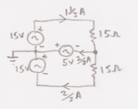
This technique works equally well for modelling the case where the
impedances to ground are unbalanced. We just make them balanced (but
same total impedance) and add an appropriate common-mode voltage.
When we talk about balanced or unbalanced circuits it must be in relation to some reference, usually earth potential. Balance not only requires equal currents, but also equal voltages with respect to earth. This in turn implies equal impedances to earth. When we have achieved this, electromagnetic radiation by a balanced line is cancelled in the far field, when referenced to earth potential (most things are!). By reciprocity, interfering currents or voltages induced on the balanced line are rejected.
In the case of an unbalanced line, provided the return current on the inside of the braid equals the forward current on the coax centre conductor, the differential mode cannot radiate. Note that it's not due to some magical screening effect (see Ampere's Circuital Law)! At first sight you might also think that this equally applies to common-mode currents, but consider the circuit below:
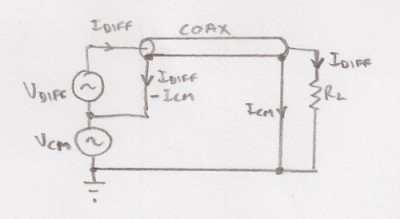
Here, the common-mode current is supplied by Vcm. Notice that only the differential-mode current supplied by Vdiff flows through the load. This is intuitively correct because the return current must equal the forward current. The common-mode current flows only through the braid. At RF the common-mode current flows on the outside of the braid, which means it can radiate (or receive).