TV rotator position feedback
August 15, 2026 - Reading time: 17 minutes
Introduction
This project involves 240V mains voltages, which are potentially lethal. If you copy what I did here, you do so entirely at your own risk.
Quite some time ago now, I had a TV rotator rotating my small loop antenna. I had originally found it at someone's garage sale, and it was very cheap. It hadn't been used at all. I must admit, I feel it's not easy to justify the expense of something like a G-450C rotator on an Rx-only antenna!
As seems to be common, some plastic cogs in the controller eventually became brittle and broke. It didn't seem easy to find replacements, and I was also less than impressed with how it worked anyway. There's an AC motor that's a duplicate of the one in the rotator, with the same gearing to the display. You set the heading and the motor(s) stop when the heading matches the display. You hope that the motors run at the same speed. 'Calibration' involves rotating to the mechanical end-stops in the rotator, causing the motor at the rotator end to stall whilst the one at the controller end doesn't.
More expensive rotators have some form of position feedback to the controller; typically a potentiometer geared/connected to the main shaft. I found that others had already managed to add potentiometer position feedback to a TV rotator:
http://www.qslnet.de/member1/dl5za/rotor/index.html
https://www.dougbraun.com/rotor_mod.html
Doug adds a plastic gear to pick up the rotation on the existing gears. This is neat, but the pot location means cutting a hole in the casing and adding a plastic cover. DL5ZA's method directly connects to the main shaft, but then cannot take advantage of the multi-turn pot. My thanks to both of these for posting their experiences on-line and giving inspiration to others.
Then we had a house extension, I lost my shack for a while, and this project got put to the back of the shelf. Mostly I use the Rx loop to null VDSL noise, so it can be pointed using the 'Armstrong' method and left. It sure would be nice to be able to tweak it from the shack again though! Five years later, this is one of those 'round to-its' I've actually got round to!
I've followed DL5ZA's basic design. Originally, I thought I would try to add a gear to the main shaft connection and another gear to the pot, so it would use more of the pot's 10-turns. After some deliberation, there isn't enough room to get sufficient gearing to make it worthwhile.
Adding a potentiometer to the rotator
The first job is to drill and tap a hole into the end of the main shaft. I found some M4-12+6mm stainless round spacers on eBay that makes for an easier transition to the 6.35mm pot shaft, so an M4 thread must be made.
This is the main shaft after removal. It's held onto the main steel deck with a circlip on the end of the shaft. There is a ball bearing race, so maybe disassemble over a kitchen bowl?!
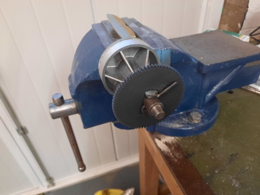
The rod welded across the main cog is the mechanical end-stop. It will need to be cut (see later). It looks like the upper part, which is aluminium, is brazed onto the steel shaft. I couldn't remove it, despite heating it up quite a lot! This complicates drilling an accurate hole in the end of the shaft.
Graeme (G0WXI) to the rescue again. He has a lathe, an offset chuck, and a collar. We added a short stub mast to the upper part. This is held by the lathe chuck. The chuck is adjusted to offset the centre of rotation of the piece so that the shaft has minimal run-out. The collar is used to provide more support around the bottom part of the aluminium as it rotates. A run-out gauge was used to adjust everything. Once this is done, the shaft can be drilled and tapped very accurately. Here's a (not very good) photo of Graeme in action:
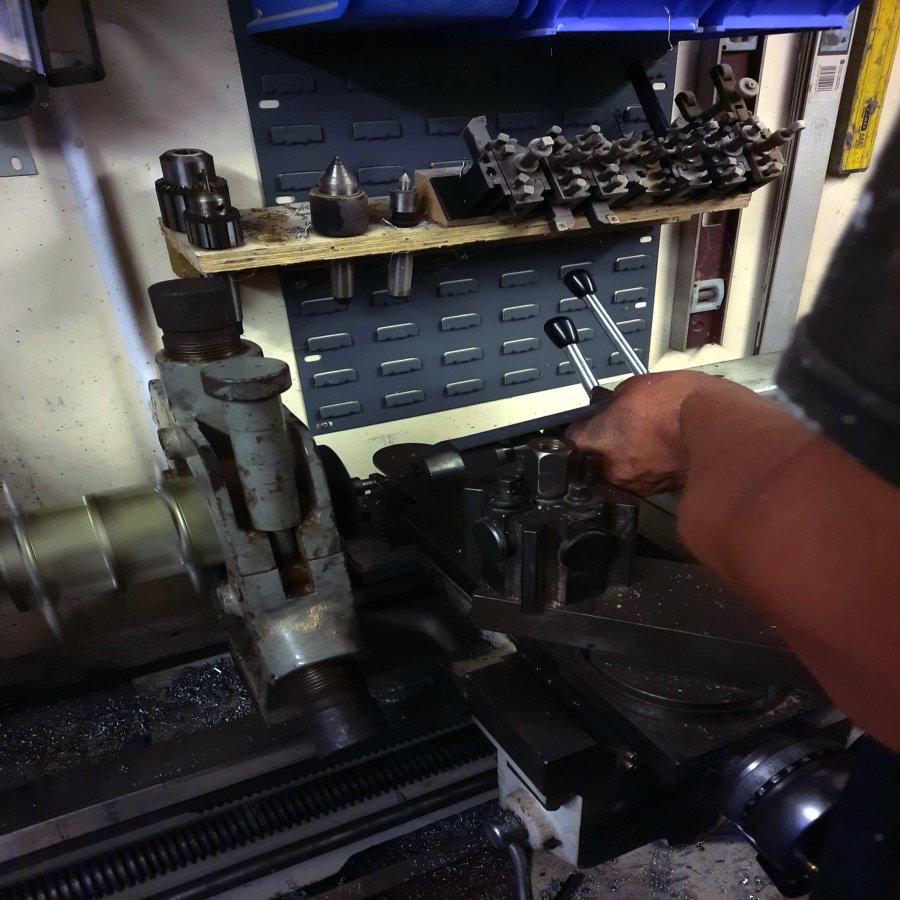
You can see the upper part of piece rotating on the left, and the collar.
It might be possible to drill manually, but then you will likely need a lot of flexibility in the connection to the pot's shaft.
This is the result, with the spacer added and the mechanical stop sawn-off. Some Loctite 222 threadlocker was used make sure it doesn't come undone.
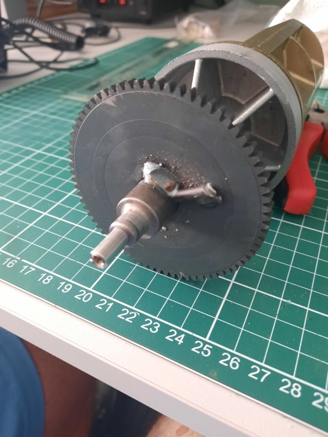
The original grease had gone hard, so it needed re-greasing. The motor also got a drop of oil on the bearings. The steel deck had some rust around the edges, so some rust-eater was applied.
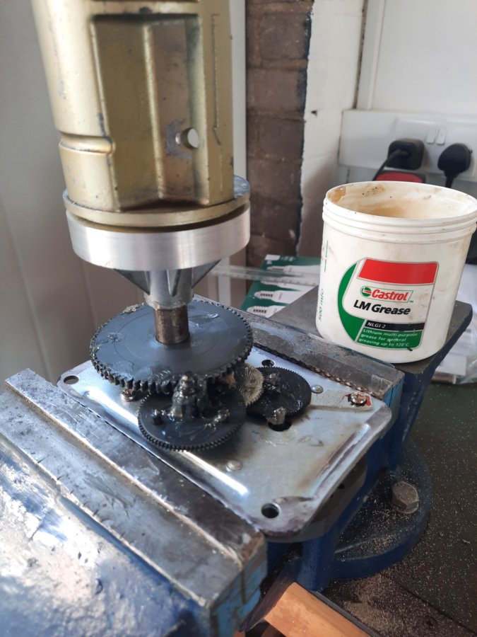
Here's the underside after reassembly:
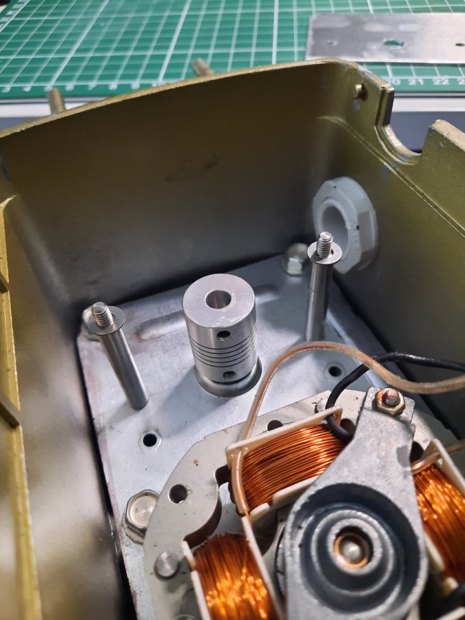
Before reassembly, the original posts that held the electrical screw connection block were drilled-out (the holes you can see). New 4mm holes were drilled in-line with the main shaft and three 6mm stacked spacers used to create a mounting point for the pot. Here you can see a flexible shaft coupler added to the 6mm spacer on the end of the shaft. It does the conversion from 6mm to 6.35mm. Additional washers are used to add a little more space. Notice that I've also added a waterproof cable gland that will take the new 6-core rotator cable (7.3mm OD).
Some 1.5mm sheet aluminium was fashioned to mount the Bourns 3590S-2-502L pot (5k linear). A penny washer on the top side gave me a little more room clearance to the shaft coupler. The pot is adjusted mid-range when the rotator is pointed north and the shaft coupler tightened.
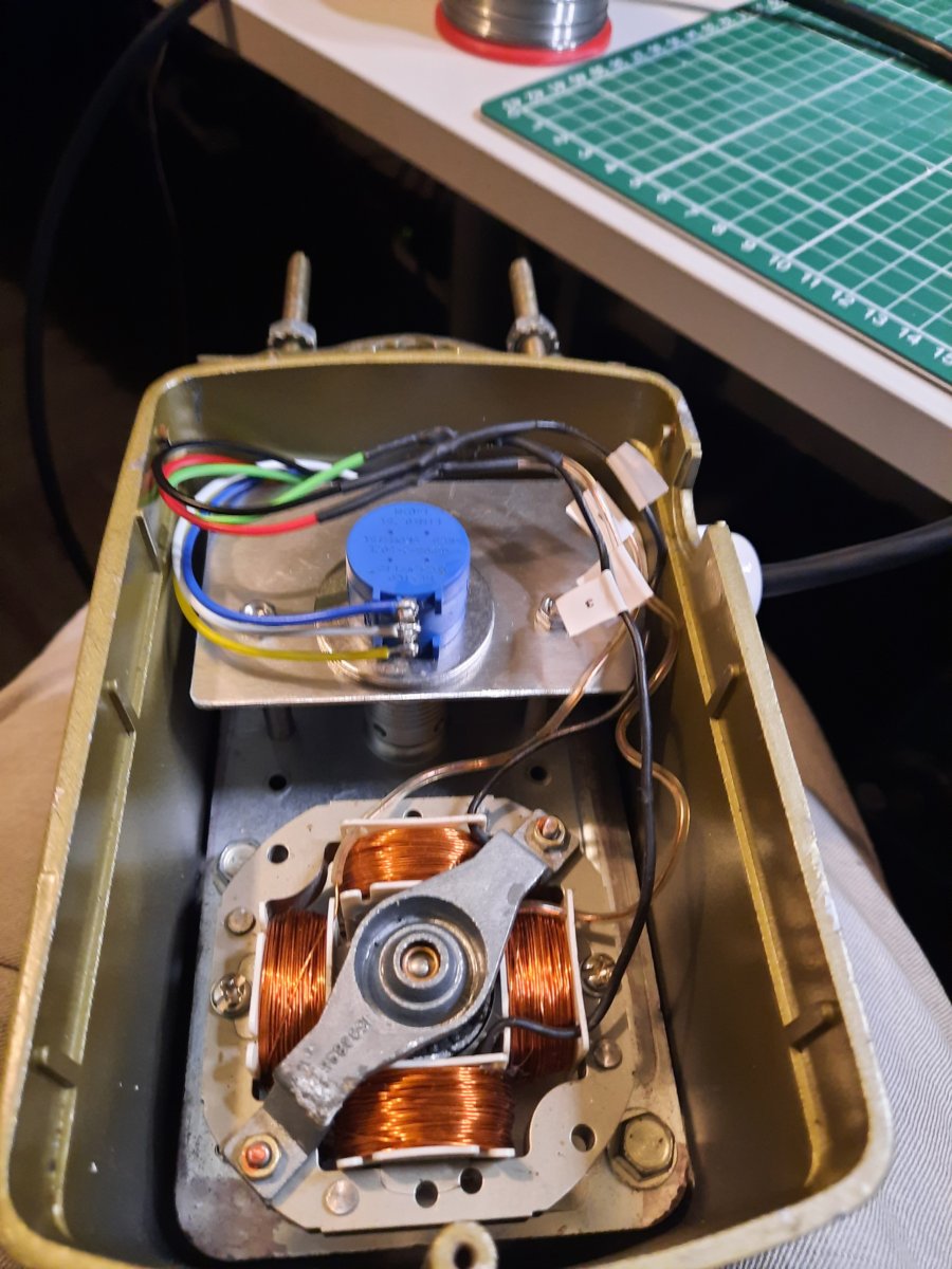
Controller
PSU
The obvious thing to do is to re-use the original transformer. Maybe mine is different, but it is not centre-tapped, as suggested by DL5ZA. There are three wires: two red and one black. I had expected the black to be the centre-tap, but it seems that there are two windings in the same sense with a common connection (the black wire). I checked this with a 'scope, which showed the two red wires were in-phase, and there is no voltage developed between the two red wires. In the original design, one of the red wires is used for one direction, and the other red wire is used for the other direction. There's no particular reason for this. The two red wires can be joined together for double the current capacity and a momentary SPDT switch used instead, like this:
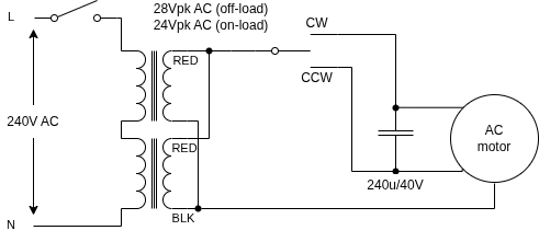
The AC motor has two windings. The capacitor causes a phase shift, so contacting the AC source to one side or the other causes a phase lag in the unconnected side. This causes a rotation in the electric field in one direction or the other. The capacitor must be rated for use in AC motor applications. I just re-used the original. The above circuit was tested for operation before going any further.
I measured 1.7A RMS current draw when the motor was running. I had in mind using some Pro Elec 16-2-6A 6-core cable for economy, since up to 100m was needed. Each core is 16/0.2mm, and the overall jacket diameter is 7.3mm. The risk is that too many volts are dropped over such a long run. The datasheet suggests 4 Ohms per 100m, and I measured 3.5 Ohms on the drum. That would drop nearly 6V from the 24Vpk noted in the figure above. That seems like a lot, so I tested using the full drum and thankfully it seemed happy enough.
I needed +/-12V and +5V for what I had in mind for the electronics. The negative rail was because I didn't want to float the DVM used as the digital heading display. If the transformer had been centre-tapped I could have used full-wave rectification even with a split supply, but because it isn't, only half-wave rectification can be used. This increases the size of the reservoir capacitor needed for a given current draw and supply ripple. I was limited by physical height (about 12mm), even though this reservoir capacitor is laid on its side. 220uF was the largest I could accommodate with 50V DC rating (I didn't put the rating in the figure below, but you obviously need 50V for safety).
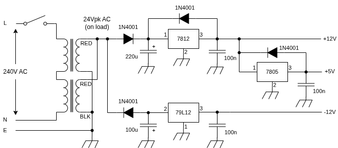
The 7812 drop-out voltage is 2V, so the input shouldn't drop below 14V. On-load (motor running) AC peak voltage is 24V, so we can allow the reservoir capacitor to drop 10V between each positive half-cycle of 50Hz mains. The max current draw can be estimated from I = C*V/t = C*V*f, where f is the sinewave period (50Hz). This works out as 110mA, which should be more than enough.
I wasn't sure how much decoupling capacitance I would end up with on the +12V & +5V rails, so protection diodes were added on these regulators. The -12V rail is only used for the op-amp, so we only need a low-power 79L12 and a protection diode isn't warranted.
A word about mounting the transformer. Because it's weighty, I fabricated a chassis out of 1.5mm sheet aluminium that was mounted in the bottom of the plastic enclosure. It had a hole cut out to get the transformer bobbin close to the bottom of the enclosure to save space. The transformer has a hole in each corner of the core that will accept a 4mm bolt. I used four M4 x 55mm bolts together with 8mm hex spacers to space the transformer from the chassis. More hex spacers are used above the transformer to both secure the transformer and to allow a copper clad-board to be attached above the transformer. Initially, the copper-clad board was not electrically isolated from the mounting bolts. This caused the transformer to get warmer than without the copper-clad board.
Here's a diagram of said transformer:
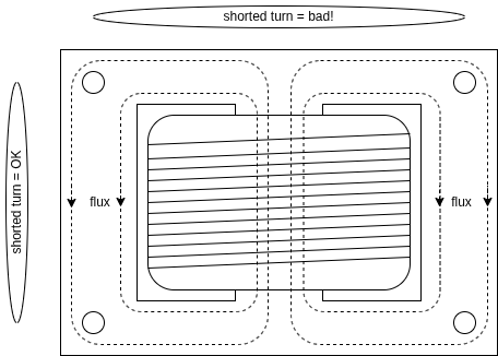
It's a conventional 'EI' type; so called because the core is made from thin sheets of steel in the shape of E and I. These are laminated (usually with varnish) to insulate them. The bobbin can be placed over the centre of an E lamination, and the I closes the magnetic circuit. Laminations are progressively added, alternating E and I until the bobbin's central hole is filled up. The coil on the bobbin has it's turns going into and out of the page, as viewed in the diagram above. When an AC current is applied to the coil it creates a time varying magnetic field that is concentrated in the core, as shown. The primary and secondary coils are wound on the bobbin, so are tightly coupled. For highest efficiency, you want the magnetic flux to tightly wrap around the coil. The ferrous core material helps concentrate the flux.
Whilst you would expect most of the magnetic lines of flux to be concentrated on the inner edge of the core, some still pass the other side of the mounting holes. If a loop of wire is passed through just one of the mounting holes, by Faraday's law of induction it will induce a time varying voltage. I actually measured this and found that 30mV was induced on each hole. In addition I passed a loop of wire around pairs of bolt holes, as shown above. The vertical loop resulted in no induced voltage. This is because no lines of flux are enclosed - they're on the same line of flux. However, the horizontal loop gave 55mV. This loop does enclose lines of flux. One way of thinking about this is that the loop is in the same plane as the main transformer primary/secondary. The vertical loop is orthogonal. It might only be 55mV, but a shorted turn through these bolt holes would cause noticeable heat dissipation.
The problem I encountered can be solved by simply insulating the copper-clad board from the mounting bolts, so as to avoid any shorted turns.
Transformers can suffer from 'eddy currents', where loops of current form in the core (perpendicular to the page in the above diagram). This is why laminations are used, to stop current flowing in that plane. We don't want to defeat the laminations, so I used nylon washers on either side of each bolt hole, and also covered the bolts with heat-shrink.
After these changes, the transformer ran a lot cooler.
Control electronics
The completed schematic is shown below:
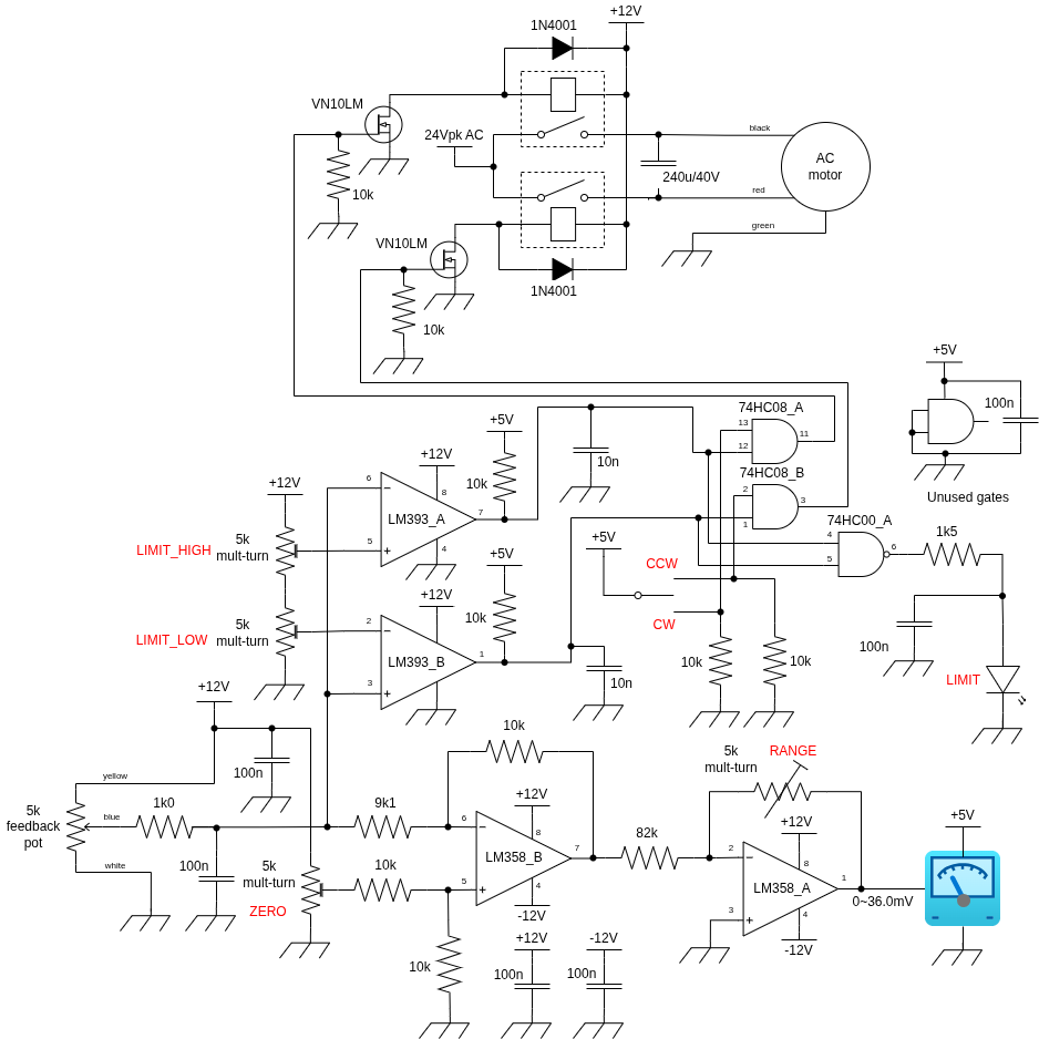
The 5k feedback pot voltage is compared to a 5k multi-turn trimmer in a bridge arrangement. A unity gain differential amplifier gives error output. By using a split-supply, the op-amp can provide a negative output. With the feedback pot centered, and the rotator set to north, 360 degrees rotation was measured to cause 1.2V change in voltage. The meter used is a Voltcraft LCD-Panelmeter 70004. There are many variants of such meters by various manufacturers, but they all have a maximum measuring voltage of 199.9mV, and can display up to 1999. The decimal point can be turned on with appropriate wiring. Because we want to display 0~360 degrees, we must scale the 1.2V change to 36.0mV. That's done with the second inverting amplifier. It's possible to combine the functions into one op-amp, but that would lead to interaction between the 'zero' trimmer and the 'range' trimmer. With the rotator at the north starting position, the 'zero' trimmer is adjusted for 0 on the meter. After rotating clockwise 360 degrees back to north, the 'range' trimmer is adjusted for 360 on the meter.
Because the mechanical end-stop was removed, I decided to add an electronic end-stop. The 'limit_low' and 'limit_high' trimmers provide reference voltages which the raw feedback pot voltage can be compared with. Within the two end-stops, the comparator outputs are both high. These are AND'd with the momentary switch to enable rotation. Beyond the end-stops, only going in the opposite direction is possible. A 'limit' LED indicates when the end-stop has been reached. What I hadn't banked on was that there's quite a lot of 'noise' on the feedback pot when rotating. This is sufficient to cause the comparators to trip, particularly near to the end-stops. You can see that I've tried to add filtering to reduce this effect. Some hysteresis on the comparators might have helped, but I think the amount required would have resulted in noticeable stalling. As things stand, the limit LED flickers a bit during rotation, and there is some relay chatter when the end-stops are reached. I think it's acceptable. You can see why commercial rotators use mechanically operated micro-switches, but that would require another two cable cores.
Initially I used some 2A solid-state relays, but these weren't man-enough, and I replaced them with some Hongfa HF49FD/012-1H12F relays. These were chosen because they would fit into the space available, and have relatively low energising current (about 10mA at 12V).
Here's a top view of the controller:
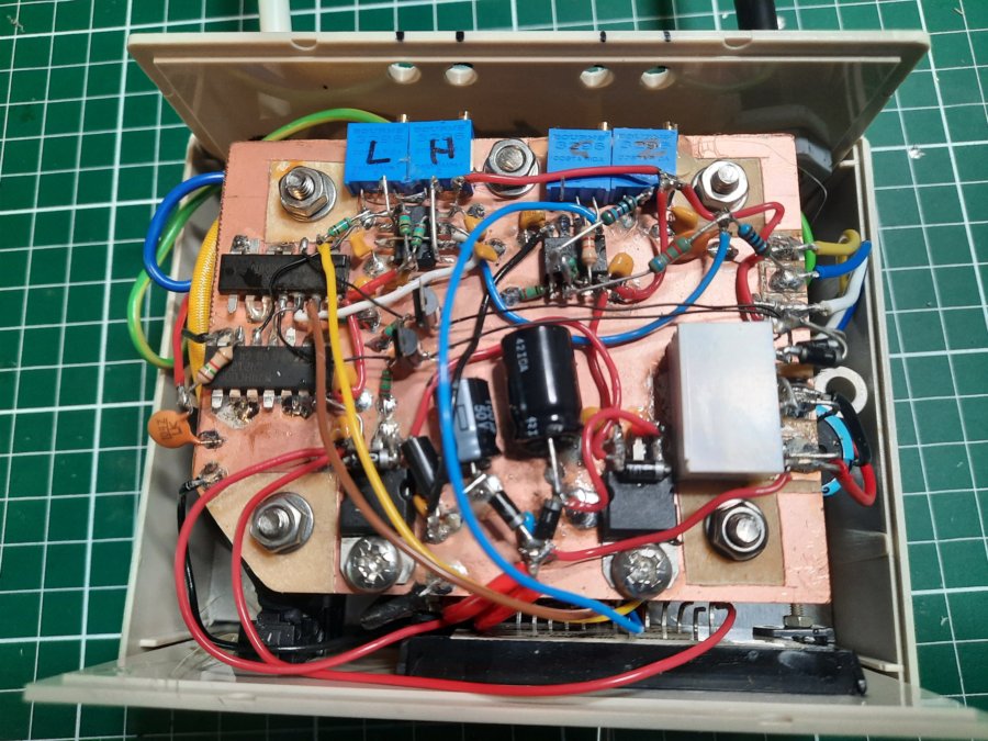
Proof that you don't need a PCB!
And here's the completed unit under test on the bench:
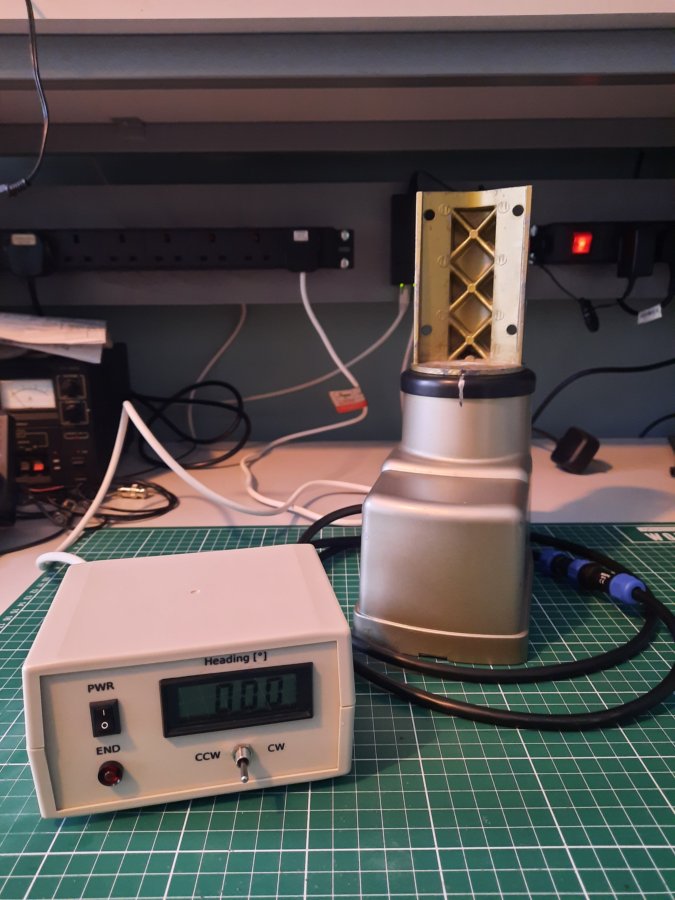
I'm using PELR0118 and PELR0139 6-pole circular in-line plugs and sockets from cpc.farnell.com. This allows the extra cable to be inserted as needed. The enclosure is a 130x100x70mm Hammond RM2015L in ABS, from rapidonline.com. The panel labels are laser decals with matt acrylic lacquer.