SJ2W Stackmatch and controller
August 15, 2026 - Reading time: 8 minutes
The well known contest station SJ2W also sell bare PCBs to make a Stackmatch. At the time of writing these were still available here. It's a copy of the standard 'WX0B Stackmatch' that you will find in the ARRL Antenna Handbook. For posterity, this is the circuit diagram:
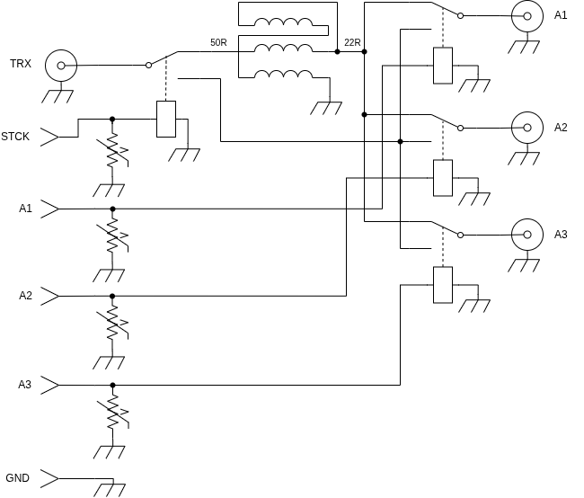
The unun has a ratio of 2.25:1 which yields a bit more than 50 Ohms when feeding two 50 Ohm antennas, and a bit less than 50 Ohms when feeding three. It's a satisfactory compromise, VSWR-wise. The core is an FT240-61. Originally I used only one core, but I had overheating of the core during the 2026 IARU contest operating as the RSGB HQ station on 15m SSB. The outside temperature was about 32C, and the Stackmatch is located in a box within a box at the bottom of the tower. The linear amplifier didn't like the rising VSWR and tripped-out. Once the core goes beyond its Curie temperature the inductance per turn rapidly reduces. I subsequently upgraded to two stacked cores, as shown below:
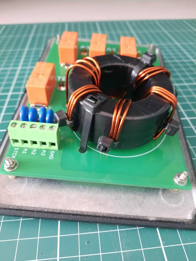
I'm using 5 turns of 1.5mm enamelled copper wire.
Probably of greater interest is how the controller was implemented, as you have to do that yourself. This is the truth table:
| STCK | A1 | A2 | A3 | ANT COMBINATION |
| 0 | 0 | 0 | 0 | A1+A2+A3 |
| 0 | 0 | 0 | 1 | A1+A2 |
| 0 | 0 | 1 | 0 | A1+A3 |
| 0 | 1 | 0 | 0 | A2+A3 |
| 1 | 0 | 0 | 1 | A3 |
| 1 | 0 | 1 | 0 | A2 |
| 1 | 1 | 0 | 0 | A1 |
The 4 control signals may be decoded from the 7 antenna combinations using simple diode matrix logic, as shown below:
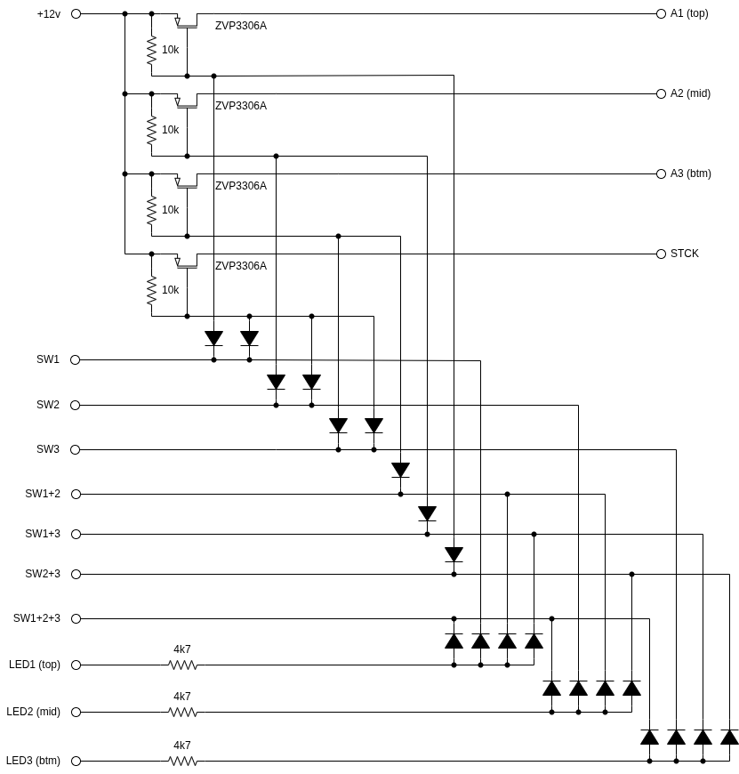
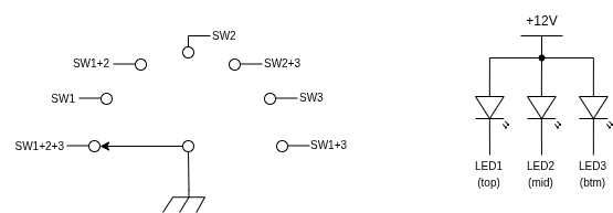
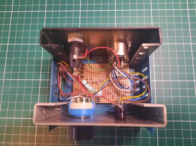
I deliberately drew the above schematic in a style that makes it easy to transfer to Veroboard. The decoding also lights the appropriate LED whenever an antenna has been selected. 1N4148 diodes were used throughout.
You can choose the rotary switch order to suit you. I wanted to have a second lower antenna on the tower pointing south during contests. This is often a forgotten direction from G, but you don't want to miss the African mults, so it's useful to sometimes listen and spray some RF in that direction. At the moment this is just a 15m delta loop, but it has still proved useful. EA is also often much louder on this antenna. I wanted to go from 'top', 'top+mid', 'mid' in adjacent steps - hence my particular choice.
I measured 69mA worst-case current draw from the 12V supply, which is well within the max rating of just one ZVP3306P (160mA).
Here's the internals:
And it in operation:
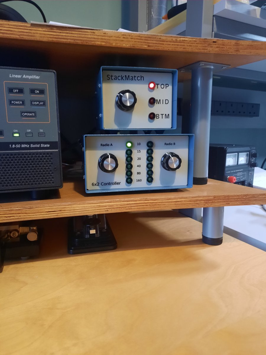
For this project I used dry rub-on lettering and then clear lacquer, but the laser decal method gives superior results, as per the 6x2 controller below it.
The enclosure is a Hammond 1458VA3B, purchased from farnell.com.


Hit Counter
- Running Total: 1,341
- Page Hits Today: 70
- Todays Vistors: 60
- Page Hits This Week: 436
- This Weeks Vistors: 301
- Page Hits This Month: 492
- This Months Visitors: 338