SJ2W 6x2 antenna switch and controller
February 24, 2026 - Reading time: 4 minutes
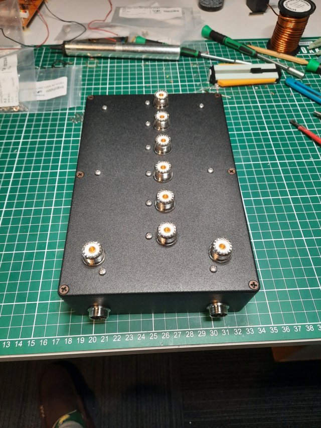
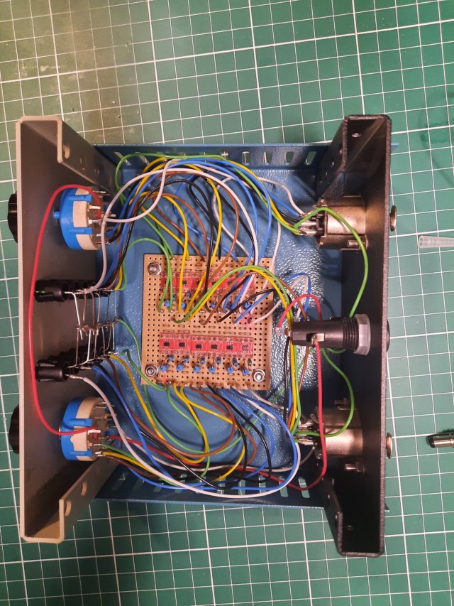
The well known contest station SJ2W also sell bare PCBs to make a 6x2 antenna switch. At the time of writing these were still available here. This is my build:
They don't sell any controller hardware, so you need to roll your own! Initially, I had planned to use ethernet control, so that I could control many things at the base of the tower with far fewer cables, but I came to the realisation that this wasn't going to happen in a reasonable time frame, so I opted to go for the classic Array Solutions style controller.
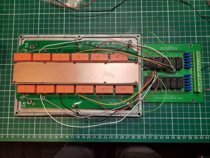
The SJ2W design has a separate relay PCB that implements 'first one wins'. This is to avoid both radios selecting the same antenna - with catastrophic consequences. When radio 1 control selects an antenna port, it disconnects the radio 2 control from the RF relay that connects to the same antenna port, and vice versa. I thought it would be neat to have a means of indicating which one had won. The relays associated with the radio that lost cannot draw current, so we need a means of detecting current flow. You cannot simply put the indicating LED in series with the control wire because there is too much current - the LED will fail. I measured about 100mA at 12V. I also found that at least 7V was required to energise the relays, and this included the full length of control cable (about 50m). This is the circuit that was used:
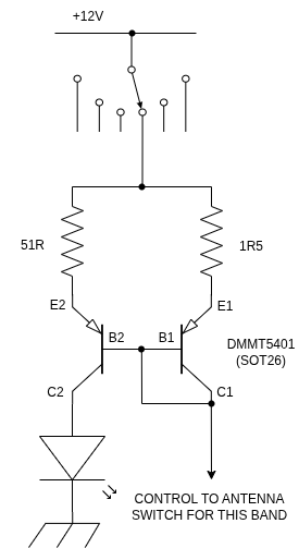
There is one per switch position, and because we have switches for radio A & B there are 12 in total.
A current mirror is used to pass approximately 1.5/51 (about 3%) of the relay current flow through an indicating LED. With 100mA draw, that's about 3mA. In IC design, you would size the two BJTs (using multiple devices) to achieve the desired mirror ratio, and emitter resistors wouldn't be needed. You can only obtain matched discrete BJTs, so only a mirror ratio of 1 is possible. Fortunately, you can drop some volts across emitter resistors and scale the resistors. If enough volts are dropped, the influence of differing Vbe is negligible. With 1R5, 150mV is dropped. Then you have about 0.7V from the diode connected BJT, so with 12V supply you get about 11.1V available to drive the relays, which is more than enough.
I used DMMT5401 devices. It's not easy to prototype with SOT26 packaged devices, but you can get small PCBs from eBay that allow you to convert to 0.1" pitch, as you can see in the photo below. Each device is rated at 200mA Ic, and 300mW Ptot. The diode connected device dissipated 0.7*100mA = 70mW, so is well within it's ratings.
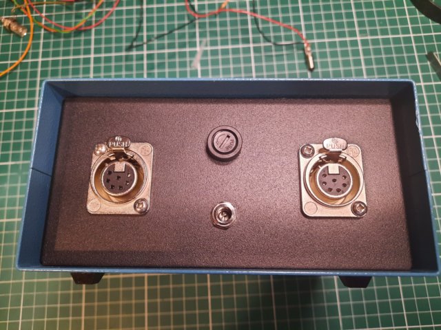
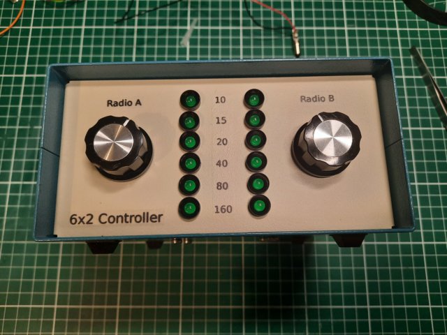
The front panel was labelled using laser decal paper. After sliding the decals on and spraying with an acrylic varnish you can hardly see the edges of the transparent decal backing. This is much more satisfactory than dry rub-on letters.
The control cable connectors on the back are locking XLR style: