VDSL noise
October 19, 2025 - Reading time: 36 minutes
A worsening problem
Treat this page as more a blog of my exploits on trying to combat VDSL interference. If you find anything useful here then I have justified writing about it.
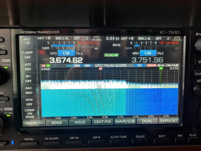
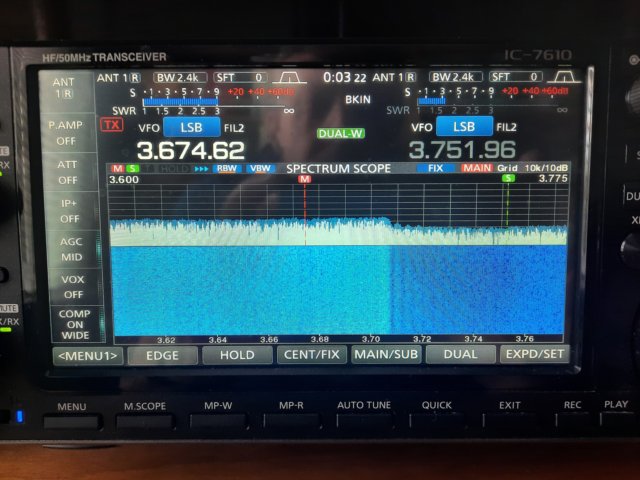
Here are two shots of 160m and 80m taken in November 2024.
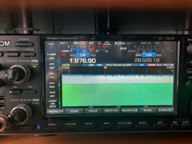
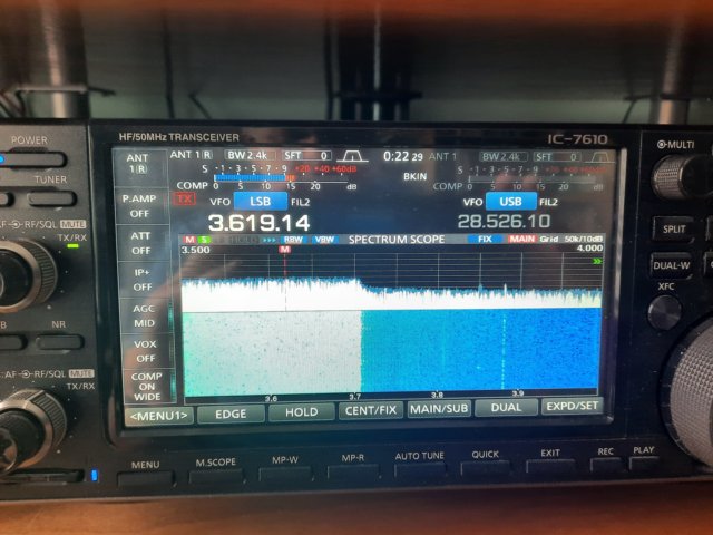
For a long time I've known I had a VDSL issue, but it has ranged from barely detectable in 2014 to now a serious problem. In fact, a year earlier I had no noticeable noise on 160m - only 80m. I know this because I try to enter the RSGB Club Calls Contest every year. I think 80m was also about 10dB quieter. If I transmit (especially on 160m) I can make it go into re-training mode, where tones are transmitted. Invariably it comes back again, sometimes after while, sometimes at a different level. There's no difference in level if I unplug from the master socket and detach the front part of the faceplate (thereby disconnecting any extension wiring). In 2025, I now know I'm experiencing VDSL on 40m and 20m, but to a lesser extent.
Ofcom complaint
In 2020, the RSGB requested all amateurs experiencing VDSL interference submit a complaint to Ofcom to demonstrate the size of the problem. In 2019, Ofcom had published a report on VDSL interference to amateurs, concluding that the problem was small because only six complaints on average were received per year. Evidently there is a reticence to report. Since my problem was now severe, I thought it behove me to submit a complaint. I used the RSGB complaint proforma and emailed it to Ofcom on 9/11/24. I supplied the photos above, and an extract reads:
The noise at 1.8MHz is equivalent to -53dBm/2.4kHz. At 3.5MHz it is -63dBm/2.4kHz. Atmospheric noise is more than 20dB quieter than this during the day. These noise levels are so high, they mean I can’t hear many stations that would otherwise be audible. I have taken all reasonable steps to minimise the problem and so I consider this to be ‘harmful radiation’.
The drop in the noise spectrum at 3.71MHz identifies it as Downstream 1. I am also able to determine with a portable radio and loop antenna that it is being radiated by the overhead telephone drop-lead. Inside my own house, I can power-down and disconnect the broadband modem, which has no effect on the interference level.
The same day, the Duty Engineering Officer responded with:
"Ofcom do not investigate cases of VDSL interference, but we will, on your behalf and with your permission, pass all details, including your contact information, to OpenReach for investigation."
Hmmm. I gave permission, which they acknowledged, and didn't hear any more until I prodded Ofcom on 9/2/25 - some 3 months later! They responded with:
"Having checked our records, Openreach replied to us on 18th November with the following comment:
'We have investigated the network in the area of the complainant, and we have identified various network impairments for which we have arranged engineering visits. These issues have now been repaired and our network is all testing ok.
Although our network is now testing ok there is evidence of home wiring issues arising on some of the neighbouring circuits. This could be down to several factors such as the use of distributed micro filters rather than a managed installation with a central splitter or star wiring in the home which can result in increased emission levels.
Openreach are not in a position to change such installations without a job being raised by the Communication Provider as this is a chargeable service. There is no further action we can take at this point.'"
I had already guessed this would be their response. Ofcom's view is that VDSL is a non-radiating technology, so any radiation is down to installation issues and therefore Openreach's responsibility. Openreach say that the problem is caused by other customer installations beyond their responsibility (the master socket). In fairness, they could hardly rock-up at someone's house and say, "your internal phone/broadband wiring is suboptimal, so we need to change it and then charge you". In my view, the failure is with Ofcom. They should have anticipated this situation and mandated notching of amateur bands. Whilst the VDSL standard includes a requirement to implement notching in the hardware, this has not been a mandatory feature for UK ISPs. I mentioned this several times in my correspondence with Ofcom, but they are well trained not to bite. Ofcom seem to want to wash their hands of the matter.
Incidentally, all email correspondence with Ofcom was copied to vdsl@rsgb.org.uk, as requested by the RSGB. It never solicited any response from the RSGB, and I later found out it wasn't being monitored. A black mark for the RSGB!
Know your enemy
Up until I think it was 2021 I was on ADSL2+, mainly through fear of what interference I would encounter with VDSL. It's a long story, but after a fault at the exchange I was advised to switch to VDSL because I was the only one on ADSL2+ at the exchange. At that time I had a fairly old BT master socket in the shack and a separate micro-filter to split telephone and broadband. The drop-wire was crimped onto CAT5 cable at the house gable end. This would have been installed by Openreach. This is the spectrum of ADSL2+ (courtesy Wikimedia Commons):
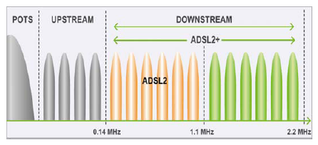
The micro-filter basically implements a diplexer function.
In preparation for VDSL, I moved the master socket to the bedroom where the drop-wire attaches to the house and changed it to an NTE 5c MK4 faceplate. The now significantly shortened CAT5 cable was also wound round a ferrite toroid to provide a common-mode choke before going to the faceplate. There was no noticeable difference in 160m or 80m noise when the VDSL switch-over happened (as I say, it wasn't so bad back then).
I can already hear the cries of 'you're not allowed to touch the master socket'. There's no law on the statute books saying 'thou shalt not touch the BT master socket'. However, it is effectively equipment that has been loaned to you by Openreach, including the cabling to it. They could claim criminal damage, but they can't do that if you move it and it all still works. What criminal damage? So my advice is, make sure you know what you're doing. I have searched, and I can find no instances of Openreach taking someone to court for successfully moving their master socket. In fact, I've since had an Openreach engineer here to investigate a crackly line, and there were no comments.
This is the spectrum of VDSL (courtesy RSGB EMC leaflet 15):
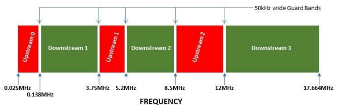
VDSL uses Orthogonal Frequency Division Multiplexing (OFDM). It's the same technology used in Wi-Fi and DAB. It comprises sub-carriers every 4.3125kHz. These are sinc functions in frequency such that the nulls occur at the sub-carrier spacing, hence 'orthogonal'. Data is aggregated and modulated onto each sub-carrier. If you look carefully at my 80m spectrum from the IC-7610, you can just about see the sidelobes after the last modulated sub-carrier. OFDM is often used where frequency selective fading is expected, because it is resilient to losing some of the sub-carriers. More on this later on.
Clearly, my problem is on the downstream side. That's also consistent with my realisation that I'm also compromised on 40m and 20m, but not on 15m or 10m. The fact that I never used to have a problem on 160m suggests to me that someone went from ADSL2 to VDSL, which might also account for the general increase in VDSL noise. There is a green cabinet about 100m round the corner from my house. I know I have Fibre To The Cabinet (FTTC). It's likely there's more than one culprit, but I think more houses that are more distant from this cabinet have also been added in recent years, which require increased downstream power. The fact that I don't have a problem with the upstream says to me that the line balance is good where my modem drives into the line, and furthermore that the subscribers generating the common-mode noise are substantially more distant than the green cabinet. I expect no common-mode radiation from my upstream because I added the common-mode choke, which forces equal forward and return signal current. The situation is different in the opposite downstream direction. All the common-mode choke can do is make the end of the wire appear to be at that point (for common-mode signals, which is what radiates). If you think about a random wire transmit antenna, varying its length doesn't change the fact that it radiates, it just changes where the current and voltage nodes are, and what impedance matching is required. To stop common-mode radiation, the choke has to be placed near the source. Apparently, it's more typical to see upstream problems, which explains why others have had success with common-mode chokes.
My understanding is that each subscriber has their own copper pair running via telegraph poles to the green cabinet. Inside the green cabinet is a Digital Subscriber Line Access Multiplexer (DSLAM). This converts the VDSL into ATM (or Ethernet) and multiplexes it onto the fibre back to the exchange. Everyone has their own upstream and downstream. There's no concept of a broadcast downstream, for example. So how do the 'issues on neighbouring circuits' end up with mine as well as other subscriber's drop-wires radiating?
ADSL micro-filter tear-down
This is the micro-filter BT supplied when I first moved-in and I was on ADSL:
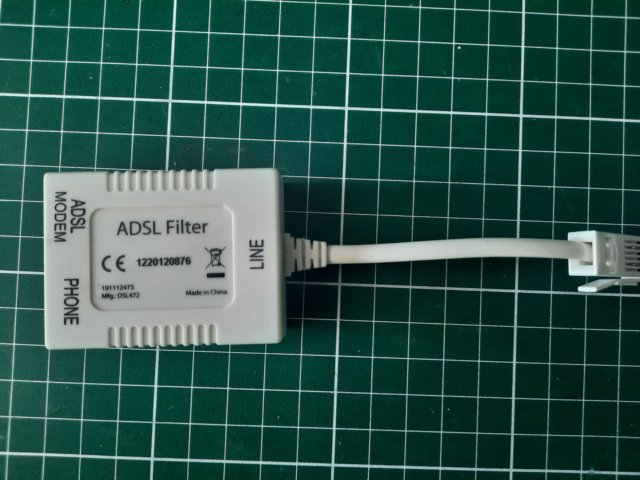
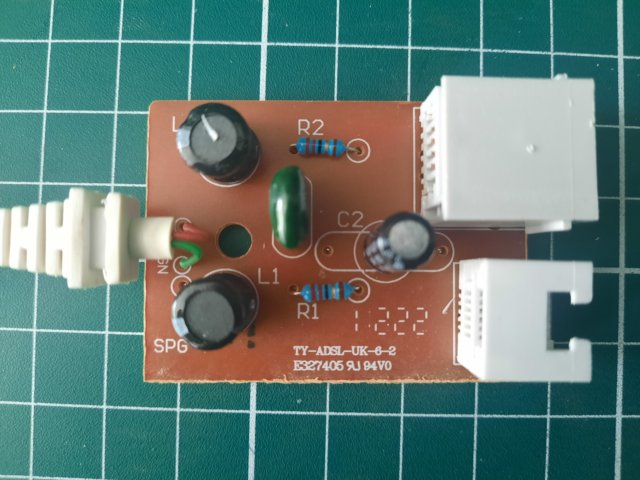
This is the extracted circuit diagram:
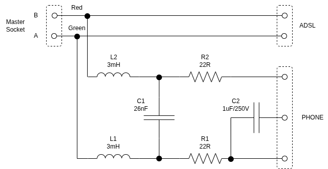
My nanoVNA wouldn't be able to go low enough in frequency, so I removed and measured the components. The two inductors go self-resonant at about 1MHz, and their DC resistance was measured as about 15R, which was modelled in the Qucs simulation below:
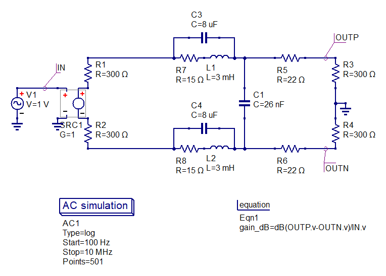
Here I've modelled 600R balanced source and load, as this is supposed to be the Zo of overhead telephone cables at audio frequencies. Apparently it's closer to 100R at higher frequencies (explaining the use of 100R CAT5 cabling from the drop-wire to the master socket). It doesn't change the result much to vary the impedance. This is the magnitude response of the Plain Old Telephone Service (POTS) line :
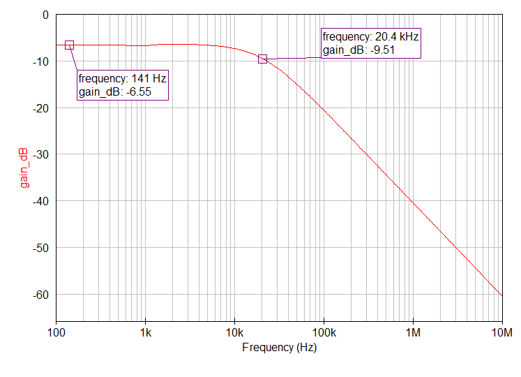
The important point is that the ADSL connection is effectively straight through. Because the inductors come first in the POTS path, they look high-Z within the ADSL band. The modem terminates the line in the ADSL band.
VDSL NTE 5c MK4 faceplate tear-down
I bought a second faceplate to tear-down. Here are the constituent parts:
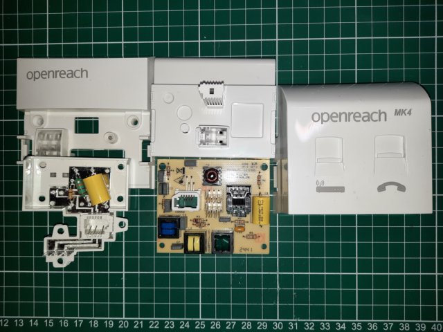
The backplate (left hand parts) allow the possibility of connecting a phone directly to the line, and it includes a ring capacitor/resistor and a 22mH series inductor on the ring line. The inductor's DC resistance was measured as 95R. Allegedly, the ring line could pick-up interference, and this was added to suppress it, but it only gets used if a legacy telephone is plugged directly into the backplate. Notice that there's no surge arrestor, which used to be included in older master sockets. When the faceplate is plugged-in, the main circuit board is attached, providing VDSL modem and phone outlets. The extracted circuit diagram is shown below:
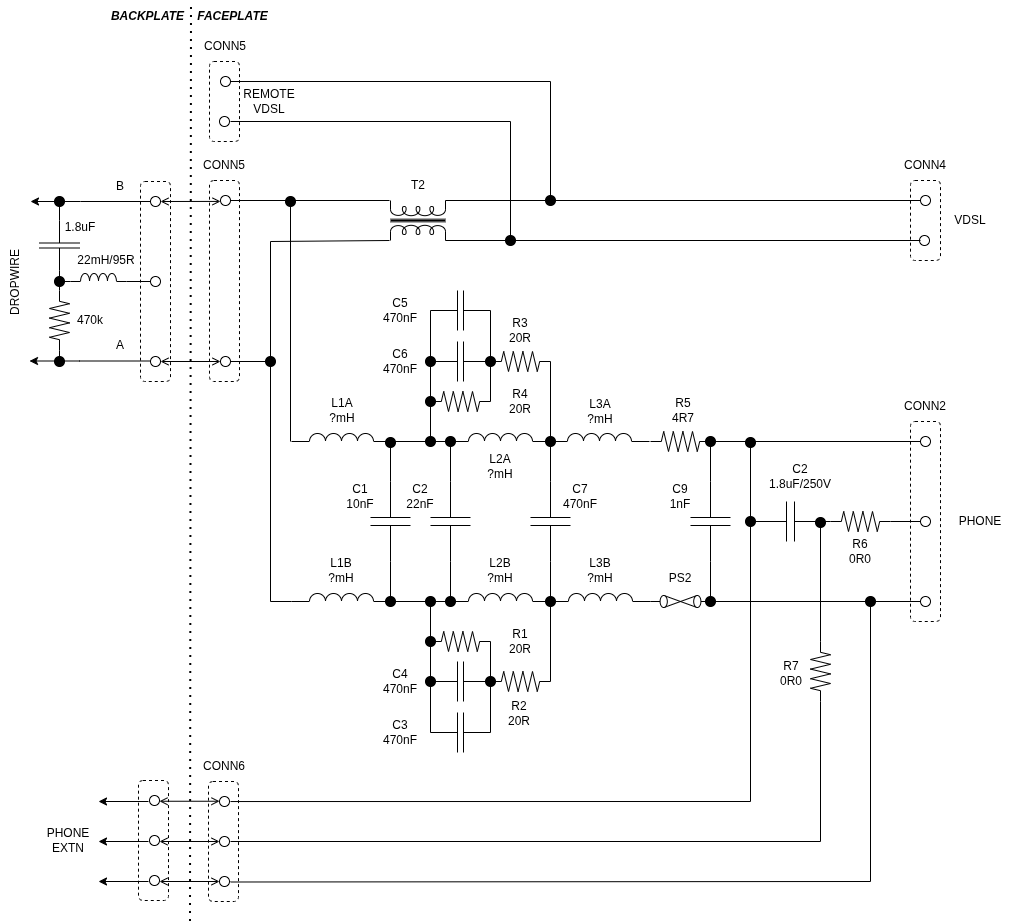
The filtered POTS line is passed back to the backplate, allowing you to add phone extensions. You connect these to the IDC connector on front of the backplate (you can see this in the photo). There is also an option to locate the VDSL modem remote from the faceplate via CONN5. This is the IDC connector on back of the faceplate (middle top left in photo).
Compared to the ADSL micro-filter, the LC filter is more complex. It's no doubt quite difficult to make a filter that has a good stop-band over the full VDSL band - notice the heavy de-Qing of stop-band transmission zeros formed with L2. I haven't bothered measuring the inductors this time.
Of particular note is the inclusion of T2. I have seen others refer to this as a Repetitive Electrical Impulse Noise (REIN) filter. In fact, it's what us radio amateurs would know as a common-mode filter. So I needn't have added one of my own! I have no idea how effective it is though in the amateur bands.
Incidentally, PS2 is a self-resetting fuse.
Openreach say that their responsibility ends at the backplate. If everything works plugging directly into that - it's your problem (or at least you'll get charged if they have to fix something beyond it). That's interesting, because it says that you can modify the main PCB if you want. You may want to bypass T2 to enable the possibility of sampling the common-mode. More on this later.
Bridge taps
In the days when there wasn't any broadband over telephone wires, it wasn't unusual to have a single overhead cable with multiple connections to it (taps) where needed to serve multiple subscribers. I'm just about old enough to remember 'party lines'. We had one, and sometimes you'd pick the phone up to find your neighbour already using the line. That would have been implemented with a bridge tap. When subscribers disconnected, the tap is supposed to be removed from the main cable. I suspect this didn't always happen, leaving a tap with an open-circuit located at the disconnected subscriber's end.
Fast forward to today's broadband world and the existence of a bridge tap causes problems. Here's a useful illustration of the problem, taken from this reference.
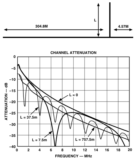
When the electrical length of the open-circuited tap is 1/4-wave, it presents a short to the main line. When L=7.5m we would expect this to occur at 10MHz, but the velocity factor of the cable is about 0.66, so it occurs at 6.6MHz. Without the bridge tap we just get roll-off with increasing frequency, as you'd expect, but with the bridge tap we get frequencies where no signal is going to get through. The plot above only shows the magnitude response. The phase will also be rapidly changing around the null.
Nulls will also occur at odd order multiples of the first null's frequency, where the electrical length of L is 3/4-wave, 5/4-wave, and so on. Physically long taps, whilst giving more nulls over the frequencies of interest, have reduced depth of null. This is because the loss of the cable means the actual impedance of the 'short-circuit' is increasing. Another way of thinking about this is that the anti-phase reflected signal is attenuated such that it can't perfectly cancel the forward wave.
This situation is one of the reasons why OFDM is used. We might lose some sub-carriers in deep notches, but it doesn't stop the whole thing from working. The modems at either end are also able to perform channel 'equalisation', to iron-out the channel's amplitude and phase response. That's one of the things going on when VDSL goes into training mode, where you can see the sub-carriers being transmitted with no modulation on them.
Apparently, the EU assumes bridge taps are not explicitly engineered to be there by the likes of Openreach, whereas in the US they do still deliberately occur.
At the time of writing, BT's broadband availability checker, allows you to see if Openreach think you have a bridge tap on your line. You have to enter your landline number to use this. However, mine just has a 'U' next to it, meaning 'Unknown'.
So why do we need to know about bridge taps? Well, let's refer back to what Openreach said about my VDSL interference situation.
Although our network is now testing ok there is evidence of home wiring issues arising on some of the neighbouring circuits. This could be down to several factors such as the use of distributed micro filters rather than a managed installation with a central splitter or star wiring in the home which can result in increased emission levels.
Probably, one (or more) of my 'neighbours' has no NTE 5c faceplate and an extension arrangement something like this:
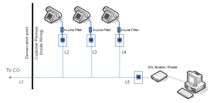
As we discovered earlier, each micro-filter will present an open-circuit to the line over VDSL frequencies. So L2/L3/L4 will introduce bridge taps. L5 won't because the line is terminated by the modem.
So my 'neighbour' probably has lousy broadband speed and frequent disconnects. But it still doesn't explain why I have a problem. I put 'neighbour' in quotes because in reality the problem is likely a distant neighbour rather than next door.
Differential to common-mode conversion and crosstalk
If the source and/or line isn't well balanced, signals in the differential-mode won't cancel each other in the common-mode. The line will radiate/receive the common-mode. This is well understood by radio amateurs who use a balun to feed a dipole antenna, for example. I have found a few references on the internet that say bridge taps can cause differential to common-mode conversion, e.g. this reference:
"Bridged taps are notorious for causing sufficient unbalance to convert enough noise from common mode to differential mode as to be a problem."
However, I have yet to see a convincing explanation of how this actually happens. It's not enough just to say that there are increased reflections, because this would still only be in the differential-mode. I can see how it might happen in coax because the inside of the coax braid is attached to the outside of the coax braid at an open-circuit (think skin effect), but the inner is only capacitively coupled. This is not the situation with balanced twisted pairs. If anyone can explain this, please get in touch! In any case, it seems to be well known that bridge taps cause unwanted mode conversion, and this would cause my neighbour's line to radiate.
Whilst my neighbour's line is radiating, this isn't the end of the story. My line will be bunched with the neighbour's and might run for an appreciable distance together. If everything was perfectly balanced, they wouldn't be able to see each other in the differential-mode. However, any common-mode will tightly couple. If my line is well balanced and free from bridge taps I won't have the common-mode appearing in the wanted differential-mode. If I did, this would cause 'crosstalk' from my neighbour's line to my line and I would notice poor broadband speed, etc. Even so, my line will be radiating the neighbour's VDSL right up to my house. I note that when I cause the interfering VDSL to go into training mode by transmitting, my internet connection is maintained. This is further evidence that my line to the DSLAM is well balanced.
Will it get any better?
In the UK, the 'digital switchover' is due to happen by 31st Jan 2027. This will mean Openreach and other providers will turn off POTS and expect you to use VoIP over your broadband connection. This doesn't necessarily mean that the local loop infrastructure will change. You may still be provided a broadband connection via VDSL over copper. The question is what my 'neighbour' will do with the extension wiring when this happens. Whilst all their extensions will stop working, I suspect they'll find other VoIP solutions and just leave the extension wiring in place. That won't help me. The master socket needs changing, and the only opportunity is when they take FTTP. Fortunately, CityFibre are building in my area. It's probably another year before it's available to customers. I have to hope the uptake is high!
Interference mitigation
Directional antennas
The best solution to my particular problem continues to be directional antennas, although I continue to explore other avenues in the remaining sections here.
On 40m I'm fortunate to have a (home made) rotatable dipole on the tower at the end of the garden. VDSL interference is minimised when beaming 30/210 degrees on the rotator dial. That suggests the interference is on a bearing of 120 degrees (because there's only fields in the opposite direction). That's not in the direction of my house by the way, but it could be my immediate neighbour.
On 160/80m I recently reinstated my WellGood loop (a Wellbrook clone) and manually oriented it for best null (I must get round to fixing the TV rotator). There is a distinct null, suggesting a single source, but this could also be multiple sources adding up in the right way. Interestingly, the null is at more like 60 degrees, but it's in a different place in the garden. When I went round my garden with the IC-705 and a portable 80m tuned loop, triangulation was inconclusive. With multiple radiators (both intentional and unintentional) it's tough to track down the actual source. I should probably try hunting it at the highest possible frequency (so, 20m in this instance).
The null on 80m gets me to within 2 S-units of the part of the band that is VDSL-free. It might be possible to do a bit better with more accurate pointing. On 160m the result is hugely better - about S8 compared to S9+20dB with the same settings as per the first photo on this page. I'm using a W7IUV pre-amp after the WellGood loop, which brings signals up to about the same level as the main antenna on 160/80m, so it's a valid comparison.
DIY frequency notching
Some people have apparently had success with adding their own notches in affected amateur bands. A simple means of achieving this is to add an open circuit 14-wave stub across the incoming line. It can be done with a CAT5 or CAT6 twisted pair of the correct length. Alternatively, a bank of series LC networks across the line could introduce notches in several amateur bands. Because the notch is in the differential-mode, it can be done after the NTE master socket (the REIN filter is in the common-mode).
The idea is to get the modems at either end to realise there's no point in transmitting over the notched frequencies. However, this will only work on your own connection to the DSLAM. Your notch can't be seen by other subscribers' modem connections. If you can get your interference problem to go away by disconnecting your modem, this might be worth trying. I haven't tried it because I don't have self-interference.
Note that adding notches in this way is effectively equivalent to adding a bridge tap, which we said was bad news. Be prepared for some reduction in broadband speed.
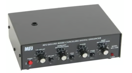
Noise cancellation
I originally bought an MFJ-1026 noise canceller when I had other interference that turned out to be two car battery chargers and an LED light in neighbouring properties. It wasn't very successful because it's dependent on getting a sample of the noise only. I seemed to be able to null the noise, but it also introduced other noise. VDSL is a good candidate for getting a good sample of just the noise, because we know it's on the phone line as common-mode.
My initial lash-up sampler used a few turns of hook-up wire wrapped around the CAT5 entering the house, as shown below:
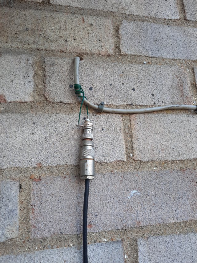
This did work, but the level was low and I had to boost it with a pre-amp (W7IUV design). I had planned to replace this with a clip-on ferrite arrangement, but I actually used this arrangement for about a year. However, it dawned on me this is effectively the end of the 'antenna' (due to the common-mode choke). Current sampling is not going to yield much signal because we're at a voltage node. Whilst I'm not a big fan of them, what we have is an end-fed half-wave type of situation. The right thing to do is to add a coupling winding to the existing common-mode transformer.
The photos below show the common-mode choke on the CAT5 cable, and you can just about see the RG58 that adds 3 sampling turns. I used my IC-705 on battery power to measure the interference signal power which allowed me to optimise the number of turns to maximise the power. I was surprised it was as many as 3 turns. As you can see, there are 8 turns of CAT5, which implies the common-mode impedance is in the region of (8/3)^2*50 = 350R. I guess it looks more 'Beverage' than 'EFHW'. I took care to do this measurement with all cables connected, and with a second common-mode choke about 4m down the RG58 to the IC-705.
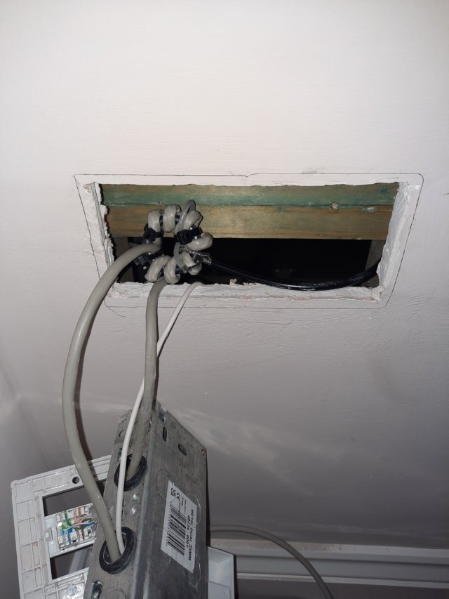
The photo on the right shows what it looks like when everything is put back. The LAN side of the modem connects to the ethernet socket (CAT6), which goes off to the router located in the shack.
I'm not keen on importing any VDSL interference into the shack, so the common-mode choke on the RG58 is retained. I used 10 turns on an FT240-43.
In the shack, the new sampler gave S9+20dB on 80m, whereas the old sampler gave S9. If the S-meter can be believed, that's 20dB difference; rather confirming the theory. It's enough that a pre-amp isn't required. If necessary, the pre-amp in the MFJ-1026 is more than enough.
As implied earlier on, if you want to copy this arrangement, you don't have to place the common-mode choke and sampler on Openreach's side of the master socket. Alternatively, you could short across the REIN filter in the faceplate (T2 in the schematic). This is easily done on the reverse side of the PCB. It might be a good idea to buy another faceplate so you can restore things if necessary. Without the REIN filter, you can make your own common-mode choke in the cable between the broadband socket and your router.
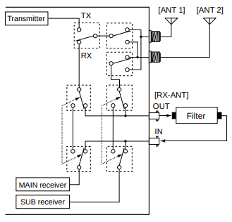
My IC-7610 has an Rx antenna in/out connection that allows you to insert something in the receive path after the T/R switching. The manual shows a filter inserted, as per the picture below. Instead, I insert my MFJ-1026 noise canceller. This method completely avoids having to use the T/R switching in the MFJ unit. Other radios have similar capability (e.g. the Elecraft K3).
The procedure I adopt is to set the main antenna gain to max and the aux antenna gain to zero. Note the S-meter reading. Turn the main antenna gain to zero and then increase the aux antenna gain until the same S-meter reading is obtained. If this isn't possible, you will have to reduce the main antenna gain from max in the first step.
Now set the main antenna gain back to where you started. Since main and aux antenna signal powers are similar, you should see about 3dB more total signal (unless you've fortuitously already got the phase shift correct). Now vary the phase to obtain a null. You may need to invert the phase. Go back and forth between aux antenna gain and phase settings to find the optimum. I find that looking at the waterfall display is easier than the S-meter. You will notice the notch moving around the band (although my notch is quite shallow). Note that the MFJ-1026 cannot do a full 360 degrees of phase shift. I found I was at the end of the phase range, but fortunately you can swap the main and aux antenna inputs to get to the inaccessible phase shifts. It does mean the pre-amp is only available for the main input, not the aux input, and obviously the gain controls are swapped. I've modified my MFJ-1026 to do the swap with a DPDT switch, which solves both these issues. See a description here.
To know how much rejection you're getting, the aux antenna gain must be reduced to zero, an S-meter reading taken, then another S-meter reading taken with the aux antenna gain restored for an optimum null. This is what I've done below on 80m:
The results are a bit disappointing. I can certainly get a minimum result, but the depth of null is scarcely 5dB here. It's easy to kid yourself that it's better than this by turning off the MFJ-1026 (which causes the relay to bypass the unit), but the main path may have loss. Nevertheless, 5dB improvement has still proved useful.
Interestingly, the ability to do cancellation has shown that I do also have a problem on 40m and 20m, because I'm able to improve the SNR.
I wondered whether there is more than one source of interference, and my main antenna is picking them up in a different power or phase relationship compared to the common-mode interference on the phone line. To answer this question I used the RSGB's Lelantos software. You can download it from this page. I used HDSDR with my IC-7610 to make IQ recordings centred on 3.7MHz with 1.92MHz bandwidth. These recordings can be analysed by the Lelantos software. Briefly, Lelantos exploits two aspects of VDSL that are not entirely random. The cyclic extension is used to obtain symbol alignment, which then allows measurement of the sync symbol. Read the Radcom article at the earlier weblink for more information.
First I took a recording of the main antenna:
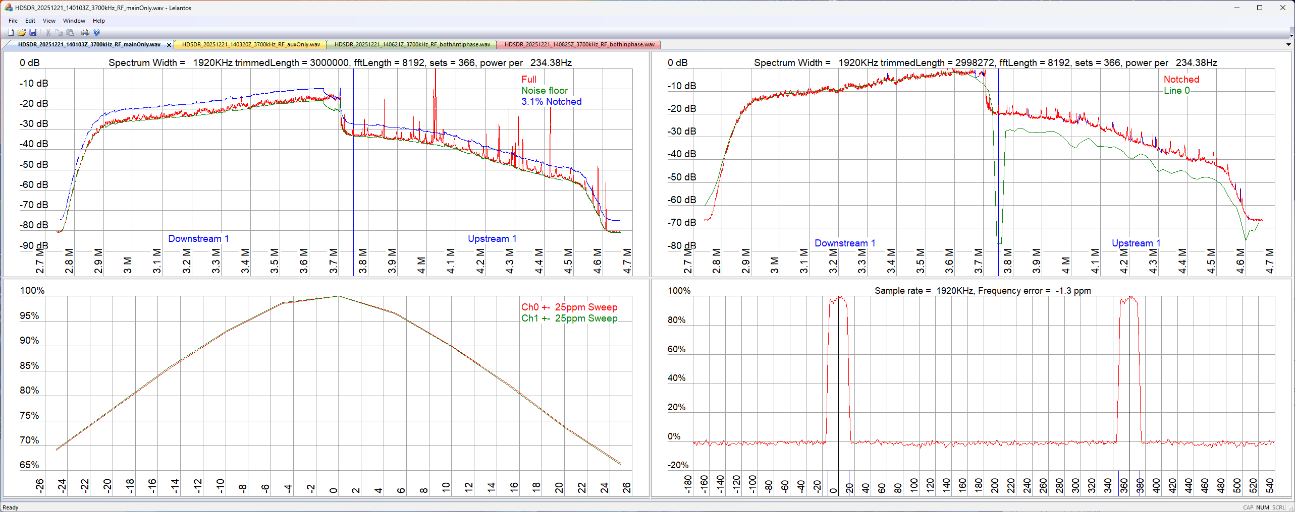
The top-left plot is the raw spectrum plot. The top-right plot is after narrowband signals have been notched (which helps detection). You can see that my antenna has 'bandwidth' because it rolls-off to the edges. Nevertheless, you can see the step in spectrum power between Downstream 1 and Upstream 1. The smoking gun is the bottom-right plot, which is the cyclic extension correlation magnitude. Successive correlation peaks are exactly at the VDSL symbol period (250us, but marked out in angle of period here).
Next I took a recording of my phone line sampler output:
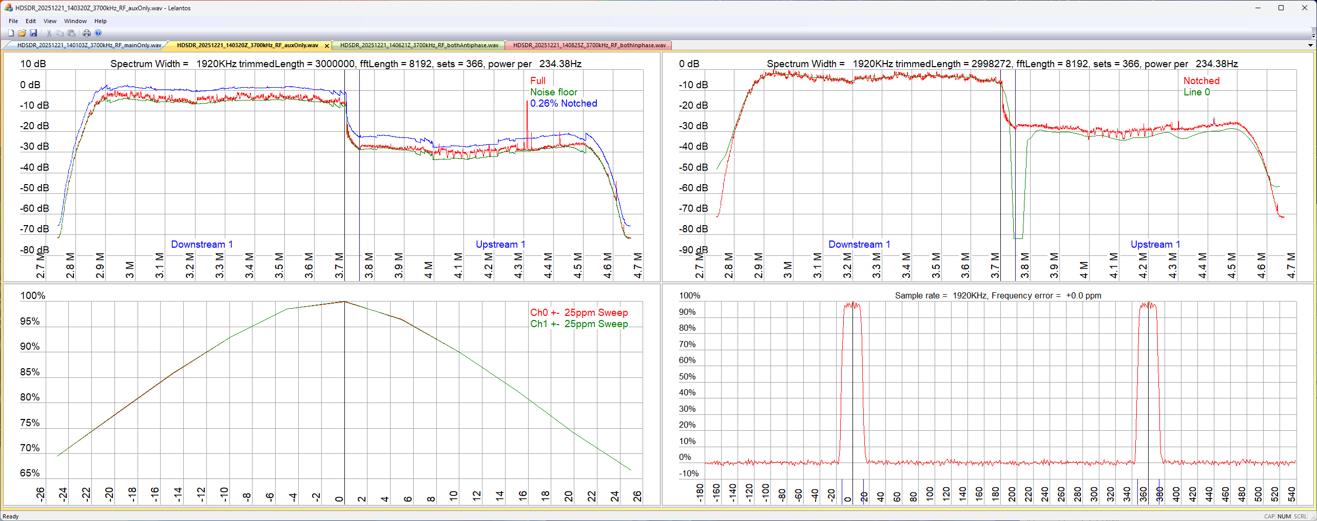
This is similar, but the spectrum is flatter (more broadband). The correlation noise floor is slightly better, which you'd expect from a mainly VDSL recording.
The above plots were obtained by setting the appropriate gain control to zero on the MFJ-1026. For the next plot I set the gains to the positions that give best cancellation, but with the phase inverted. Lelantos should see both signal paths equally well:
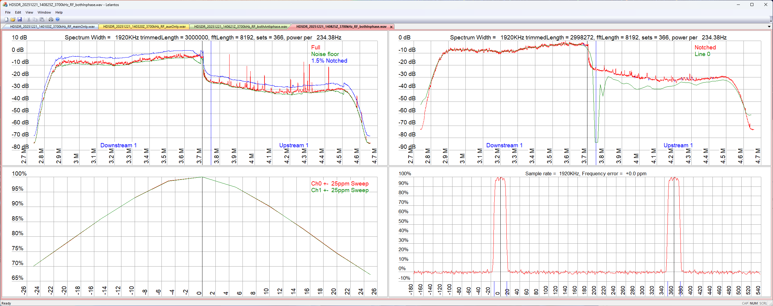
There appears to be VDSL signal enhancement in the 80m band - which is what you'd expect.
Finally, the MFJ-1026 is set for optimum cancellation:

You can definitely see there is some nulling.
What's striking is that there is only one correlation. Because customer modem start-up is random, you tend to get a random timing relationship between VDSL streams. Here's a typical multiple VDSL interference plot from the Lelantos instruction manual:
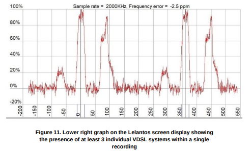
Therefore, the only conclusion I can draw is that there is only one dominant source of my VDSL interference. So why can't I achieve better cancellation? I have some thoughts on this, but need to do some experiments first.
Experiment 1: I took just the interference sampling input (aux) and jumpered across to input it into the main input instead of the usual antenna. I found I could get a null so good that it didn't move the S-meter, compared to S9+10dB without cancellation (the experiment was done during daylight hours).
Experiment 2: The same as experiment 1, but using only the usual antenna into both inputs. Again, I was able to obtain a pretty much perfect null.
These two experiments prove that it's possible to obtain a good null if the two inputs are correlated. There's nothing limiting the null in the MFJ-1026.
Experiment 3: As per experiment 1, but adding 30m or so of coax between the aux input and the main input. Again, I was able to obtain a very good null.
Experiment 4: The coax to the main antenna was disconnected at the feedpoint and used instead of the 30m length in experiment 3. I got identical results, so there's nothing special about its length.
The reason I did experiment 3 &4 was to see if differing lengths of coax from the interference sampler compared to the main antenna would give enough time delay that the VDSL interference wasn't so well correlated. Time delay is not necessarily the same as phase shift. The result suggests this isn't the problem - leaving me still scratching my head! What is noticeable is that the longer the delay between the interference sample and the main antenna, the sharper the null in frequency. With no delay it's possible to get quite a broadband null. This makes sense because we expect longer delays to show better correlation at lower frequency offsets. In January 2026 I switched back to just an 80m dipole, which has a similar coax length compared to the VDSL sampler. It still cannot completely null the interference.
I did think about buying an RSPduo, which is a dual synchronous SDR. With SDRconnect (or SDRuno) it's possible to combine the two receivers in any gain/phase combination to null a signal. This is essentially doing the same thing as the MFJ-1026, so there is no added benefit, but it would be possible to take a synchronous I/Q recording and I might have a chance of figuring out how to do better cancellation. DSP opens up the possibility of combining the interference sample at multiple delay positions using a FIR filter, and the filter weights can be found using the LMS algorithm (a primer here). A science project for when I have substantially more time!