

Disclaimer: if you decide to copy any of the things I did here, you do so entirely at your own risk. If you are not completely confident you know what you are doing consult a qualified electrician.
We now have several touch sensitive lamps in the house. An example is shown below, which was bought from Next retail:

I didn't find these to trouble me with respect to noise interference (some do), but I did annoy the rest of the family with the lamps cycling through their brightness settings either on speech peaks or in sympathy with my CW. Apparently it was like a nightclub when I operated! I wasn't 'allowed' to convert these lamps to two brightness settings (i.e. on and off), so I thought I would try to improve their immunity.
There are a couple of very useful QST reprints available to anyone located here: http://www.arrl.org/touch-lamp. One of the authors had traced out the circuit, and I decided to do the same for my lamps. The latest version of my modifications have also been added.

If you want to modify your lamp, I suggest you trace out the circuit for your controller too, so that you're certain where to modify it. There are probably a plethora of different manufacturers of control units.
These lamps appear to work by creating a low frequency oscillator and using the lamp chassis as an antenna connected without isolation to this oscillator. In the steady-state it doesn't matter what the oscillation frequency is, but when the user touches the chassis/antenna it causes the oscillation frequency to shift and this is detected, advancing the brightness state machine, which in turn controls the brightness using a triac. Is there any wonder that even a whiff of RF causes them bother? A friend at work noticed that even his power drill would turn them on!
Notice also from the schematic that there is no protective earthing of the lamp's chassis, which could defeat intended operation. I think the reason they used two 1n class-Y capacitors in series was to be double-safe. If those capacitors go short, you've got the neutral supply connected to the chassis. In fairness, this would only be dangerous if there was also a neutral fault (normally it should be quite close to earth potential), but I'm still surprised this sort of circuit is allowed.
The first thing to do with these lamps is to disconnect the chassis from the control unit completely, preferably at the PCB so there's the minimum possible antenna connected. If your transmissions no longer trigger the lamp you've got a chance of solving the problem. A plastic base plate is hot-melt glued onto the internal plastics and a felt disc stuck over this. Once removed, you can see the controller in its plastic enclosure:

Without its plastic enclosure it looks like the photo below. In this case, the chassis is connected via the brown wire. You need to unsolder this at the PCB (with mains disconnected!!) and then test its immunity.

Assuming this test was a success, you now need to make the oscillator 'feel' you touching its antenna at a couple of 100kHz but not at 1.8MHz and above, which implies low-pass filtering is required.
Normally, there will be a resistor in series with the 1nF capacitors, but probably only a couple of hundred ohms. The simplest of low-pass filters could be realised simply by adding capacitance between the IC input and local ground (neutral in this case). This is worth trying first because it's likely to be quite easy to fit a ceramic plate capacitor on the reverse of the PCB, as shown below. Try a value of 220pF, and increase the series resistor to 4k7.
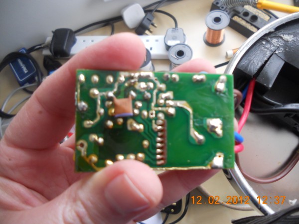
If that's still not good enough, try adding a 2.2mH inductor in series with the 4k7 resistor. If you look closely at the photo of the PCB top-side above, you might be able to spot that I've done this.
If you find that the lamp becomes unable to sense your touch you need to decrease the series impedance or increase the shunt capacitive reactance. I'd recommend concentrating on the series elements. You need to be a bit careful of your inductor choice because above its self-resonant frequency you'll get reducing rejection, as opposed to more. The series resistor helps in this respect because even when the inductor becomes a short you've still got the RC pole.
Unfortunately, one of my lights (using a Där Lighting controller) exhibited instability for any useful amounts of shunt capacitance. This manifested itself as spontaneously deciding to cycle round the brightness settings. A more robust solution was to move the decoupler to the other side of the 4k7 resistor. The disadvantage of this is there now isn't RC protection at frequencies beyond the inductor self resonant frequency. If you find you need still more isolation, it's possible to add extra LC low-pass sections to increase attenuation at high frequencies without compromising touch sensitivity.
Note that the added filter capacitors don't need to be class-Y provided they are added to the controller IC side of the 1n series coupling capacitors.
I'm sure my values aren't optimum, and they probably depend on the specific lamp controller, but I have cured my lamp problems at the 100W level, with a low antenna that goes right over the roof of the house.
Hopefully this might inspire someone to have a go at fixing their touch sensitive lamps, rather than replacing them. I should also say that you shouldn't be doing any of this to a neighbours lamp, which could open you up to a world of legal problems if anything went wrong.