

I had bought a 12m Spiderbeam pole to be used by Granta CG in the SSB Field Day Contest but I also wanted to press it into service as a (mainly LF) vertical at home. This article describes some of the construction details that might be of interest to others.
Background
I previously had a 40m 1/4-wave vertical using a 9m fibreglass pole, but this was at the bottom corner of the garden adjacent to the fence and behind the shed. This restricted me to a single earth stake and two 1/4-wave radials at right angles. Clearly sub-optimal but nonetheless it proved far better to DX compared with a 116ft inverted-vee doublet at 35ft over the house. Not just on signal-to-noise but also on DX signal strength. It was also superior on 80m as a DX receive antenna. The SWR on 40m is very close to 1:1 and very broadband. If an ideal vertical has a radiation resistance of 35 Ohms this implies that the antenna is only 70% efficient. Sounds bad, but this only amounts to 1.5dB lost.This was an interesting result because I previously used the same 9m pole atop a 15ft wooden post, creating a 40ft vertical mounted 5ft above the ground and with two 33ft radials running along the top of the fence line. In this instance the vertical was more centrally located along the fence so that the radials were in-line. This was not as good as the ground mounted vertical. Modern thinking would say that two elevated radials should yield a far more efficient antenna. It's possible that feeder radiation may have played a part in this, but if so then I would say it is very difficult to control because I did use a RadioWorks ferrite line isolator as a precaution.
Buoyed by the success of such a simple vertical I wanted to make further improvements and extend operation to other bands. I realised that the only way to better this situation was to mount the vertical in a more central location in the garden, so that I could get more radials down and in all directions. Aesthetics dictate that it can't be located in the middle of the lawn, so some compromise has to be made. In addition, the garden is only 31ft wide, so radial length is going to be less than 1/4-wave, even at 40m. This isn't such a big deal because the effectiveness of a radial ground system reduces with distance. It's much better to have lots of short radials than just a few long ones.
Ground socket
The Spiderbeam pole has the very nice feature that a 2" OD aluminium TV tubing is a perfect fit inside the bottom section and butts against the second from bottom section. My first thought was to concrete-in an aluminium pole to act as the base. However, given its central location, I wanted an arrangement where I could remove the pole and see nothing sticking out of the ground; in case future requirements demand its demise! My other concern was that I wanted the whole of the mast to be non-metallic, so that I don't have to worry about keeping the antenna wire spaced from it.I discovered that Moonraker (and others) supply 2" OD thick-walled fibreglass tube in 2m lengths,which solves the metallic issue. The perpetual pole issue would be solved by creating a 2" socket concreted into the ground.
My local metals warehouse (Mackays of Cambridge) stocked 2.25" OD 0.125" wall aluminium tube. In my naivety I thought the 2" OD fibreglass tube would fit inside this - it didn't. I guess you need some clearance. I'd already bought it, so I solved this issue by cutting it in half. Even then, it required some 'blacksmith' work to bend the ends out and increase the radius of curvature. The photo below shows a 500mm length of this aluminium tube fitted to the bottom of the fibreglass tube. The grey PVC tape running longitudinally down the tube covers up the cut slot. There is another on the other side of course. This is going to be concreted into the ground, so the tape also stops the concrete getting to the fibreglass tube.

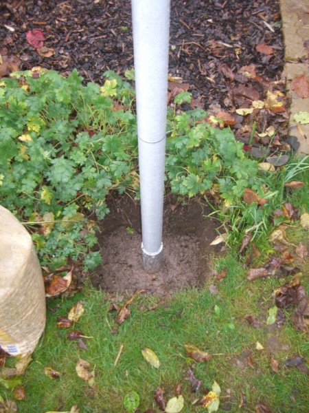
The hole was dug about 250x250x500mm deep. A 4ft earth rod was driven into one of the corners at the bottom, bolted to an earth cable and sealed with self-amalgamating tape. At the point where the pole will sit, a tile is placed with a hole drilled to allow any water to drain. This creates a non-abrasive stop for the bottom of the pole. This is all shown in the photo below.

Two bags of ready-mixed concrete were necessary to fill the hole. The pole was maintained in a vertical position using a spirit level by a helper (my daughter) whilst the concrete was poured. Here it is as the concrete sets, with a bag of shingle ready to finish off later on.
Radial plate
The radial plate was based on the design by DX Engineering, using 1.2mm stainless steel sheet from my local metals warehouse. Here it is drilled and ready for some hacksaw work.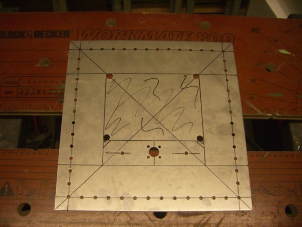
Once the middle section is removed, the connector flange must be bent vertical. This is just about possible with the Black & Decker Workmate, blocks of wood, and a hammer. Here it is completed:
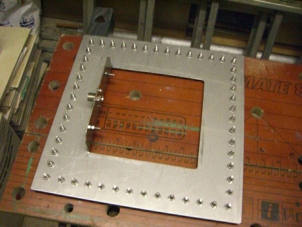
The radial bolts are all M5 stainless steel from www.stagonset.co.uk, whose service I can recommend. You'll see there are positions for a total of 52 radials, which I thought was quite optimistic! One thing I'd change with hindsight is for this not to be an even number. Assuming you don't lay all the radials at the same time, you really want to repeatedly bisect the angle made by existing radials. The obvious thing to do is start with a radial at each corner, but you can't put another mid-way between these. Believe me, this becomes a serious problem when you get a lot of radials down! I ended up abandoning this approach and instead used a garden cane placed over the bolt with one end at the spiderbeam pole. This then marks-out the direction for the radial. Note, however, that the pole must be dead-centre in the radial plate for this to work reliably.
Something else that became more obvious as I put more radials in was that a square radial plate with even distribution of the bolts around the perimeter results in a higher concentration of radials towards the corners.
40m Trap
I decided I would use a trap to provide a 40m 1/2-wave because I will need some loading on 80m, and avoiding base-loading for 80m would be slightly more efficient. The remainder of the required 80m loading would be done capacitively. The trap is of the coaxial variety that you will find documented in many places on the internet. I made mine using 32mm waste pipe and RG58. Resonance was set to 7.1MHz using a FET dip oscillator.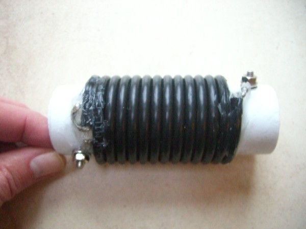
Completed vertical
Here's a picture of the vertical a few weeks after using it in the RSGB Commonwealth Contest 2012.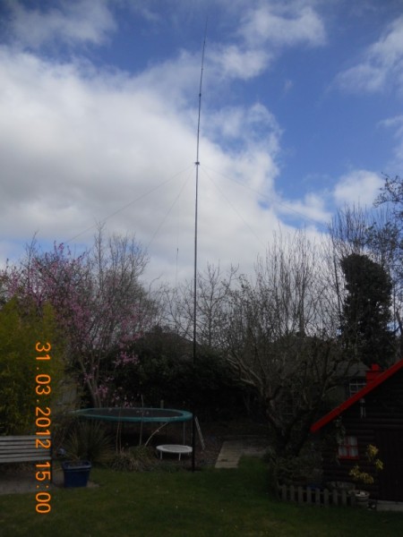
If you look carefully to the left of the pole, below the guying point, you can see the insulator for the 20m element of a 20/15/10m fan of 1/4-wave verticals. This is manually switched over at the feedpoint (a bit of a pain during the early morning opening to VK/ZL). The fibreglass sections are held in place using the Spiderbeam supplied hose clamps. The guy webbing and guy rope are also from Spiderbeam. Originally I didn't guy it, but with the top wire being very light and tied to the back fence using monofilament fishing line, reducing its movement helps stop it getting tangled in the trees in high winds.
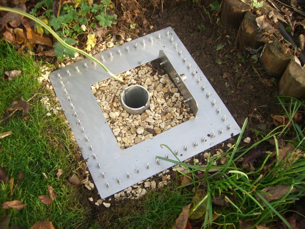
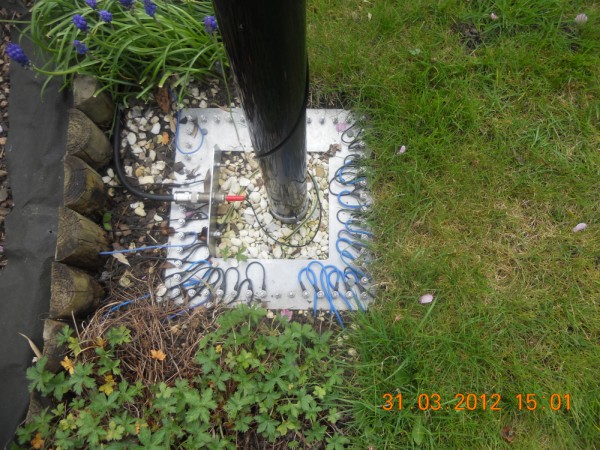
The radial base (below) currently has 35 radials attached to it. Heatshrink tubing over the ring tags helps keep corrosion out. You may notice that I replaced the standard SO239 chassis socket with a female-female version. This allows me to use a 4mm plug, facilitating easier switch-over between LF and HF verticals.
Radial locations
The drawing below shows the current radial positions as of March 2012. The drawing is to scale and was generated using QCAD. The indicated dimensions are in cm.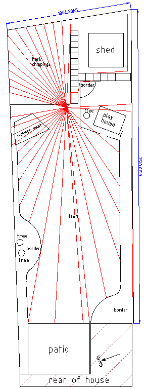
It looks like I have quite a lot of radials, but remember that the garden is only about 10m wide (33ft), so quite a lot of those radials are only 1/4-wave at 20m. Clearly I need to put a lot more effort into the South and South-Easterly directions, but this is difficult due to the obvious obstructions. I'm considering adding earth stakes at the end of some of the shorter radials, which I think should help. I'll report on that when I get round to it.
The radials in the lawn were inserted below the surface using an edging spade and an old flat file to push the wire into the slit as I went along. This is time consuming, but simply laying them on the surface and letting the grass grow over them wasn't an option because I frequently need to scarify the lawn to remove moss.
Measured impedance
The plot below shows the raw Smith chart output from a miniVNA,
measured on 28/03/2012 at the base of the LF vertical. For reference,
we hadn't had a lot of rainfall during the preceding winter months,
but the VSWR doesn't seem to change much over the seasons anyway.
The marker nearest 50R is the 40m resonance, and the blue marker the 80m resonance.
The 80m marker is at about 35R, which is where the 40m marker would be if the loss resistance was zero. Since the marker is to the left of the 50R normalised centre, this implies I'm giving up less than 1.5dB in ground losses.
On 80m, the shorter effective height will reduce the theoretical radiation resistance. I need to do some NEC simulations to establish what to expect. Prior to this measurement I didn't know whether the higher VSWR on 80m was due to the real part of the impedance being higher or lower than 50R. It's good to know it's lower than 50R because this suggests the ground losses plus IR losses in the antenna wire and trap aren't as bad as I'd feared. It will be interesting to measure the antenna again when I get round to adding more radials.
Out of interest, I also measured the HF vertical fan at the base. The VSWR plot directly from VNA/J is shown below:
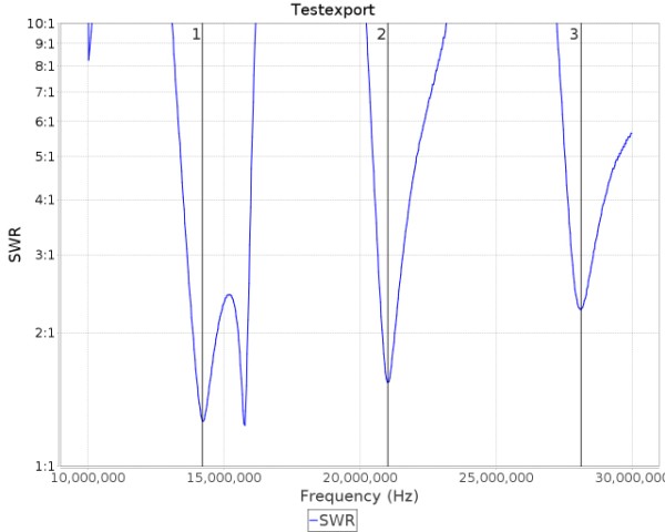
There's what appears to be a double resonance around 20m, and the VSWR gets progressively worse with band. The output from Zplots is shown below:
This is one of those situations where Zplots can't guess correctly because there are two different types of reactance sign change. The problem is that there's a tight resonance loop to the right of 50R on 20m, which is responsible for the double resonance effect. This might be due to interaction with the disconnected 80/40m element.
The blue marker is on 20m, the red on 10m. The 15m resonance is between the two of them. The VSWR minimum is not actually at the point of resonance (zero reactance), which may surprise some. I'd say 20/15m are about where you'd expect them to be, which is very similar to the 40m impedance result above, but 10m is way lower an impedance than you'd expect. I have no explanation for this, other than that there must be a good deal of interaction between the elements.
I did wonder whether the impedances might be lower than at 40m, simply because the radial screen is electrically larger at these frequencies. Discounting the 10m result, there doesn't seem to be a noticeable difference.