This page is a 'work in progress'. It catalogues my interest in receive only broadband active loop antennas.
Loop antenna theory
According to Faraday's law of induction, a time varying magnetic field gives rise to an induced emf in a closed loop of wire. The magnitude of that voltage depends on the strength (density) of the magnetic flux that the loop encloses, and therefore also the area of the loop (A). For a given length of wire, the area is maximised by using a circular loop. Adding more turns (N) in series increases the voltage in proportion.

What's not so obvious from Faraday's equation is that the rate of change of flux corresponds to the signal frequency, and so the voltage magnitude increases in proportion to frequency.
In addition, for a given magnetic field strength (H), the magnetic flux density (B) depends on the medium's permeability. Typically, we reference the permeability to that of a vacuum, using relative permeability. This accounts for the increased sensitivity that a high relative permeability ferrite rod imparts to a simple AM radio.
These observations are encapsulated in the following equation describing the magnitude of the induced voltage:

Where v and H are rms quantities.
An unavoidable consequence of making a loop of wire is that it possesses inductance. There's a good overview of appropriate formulas at http://www.qsl.net/in3otd/rlsim.html. A formula attributed to Grover for a single rectangular loop (FW Grover, "Inductance Calculations: Working Formulas and Tables", D Van Nostrand Co., New York, 1946) is shown below:

Where a and b are the length of the sides and d is the wire diameter (all in meters).
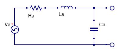
We also have some resistance attributable to radiation resistance and loss. And we also have some stray capacitance (which might be large if the loop has an electrostatic shield).
So the Thevenin equivalent circuit is as shown below:

If we were to resonate the loop, by adding capacitance in parallel to Ca such that the capacitive reactance (XCa) equals the inductive reactance (XLa) at the frequency of interest, the current that flows is limited only by Ra. The voltage developed across Ca (assuming an infinite load resistance) is that current multiplied by XCa. Thus voltage 'magnification' of Va occurs through the ratio XCa/Ra, which is the definition of quality factor (Q). More commonly, since XCa=XLa, and Q tends to be dominated by inductive losses, Q is defined as Q = XLa/Ra.
In practice, large values of Q are required if active amplification is to be avoided, which results in narrow bandwidth. At low operating frequencies it might even compromise speech bandwidth!
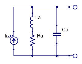
Of more interest in broadband loops is the Norton equivalent circuit. The impedance seen at the terminating port is obtained by removing the voltage source above and replacing it with a short-circuit. The current (Ia) is obtained by shorting the output and calculating the current that flows, i.e. Ia = Va/(Ra + XLa). Notice that XCa does not appear in the equation because it has been shorted-out. The resulting Norton equivalent circuit is shown below:

If the output current is sensed in an ideal short-circuit termination, all of the current must flow through this termination and not through La, Ra, or Ca (hence the calculation of Ia above). Remember that Va ∝ f, and since XLa dominates, which is also ∝ f, Ia is flat with frequency!
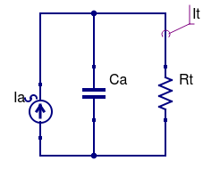
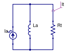
So what happens if the termination isn't an ideal short circuit? To simplify the analysis we shall separately consider the high frequency response and the low frequency response, the total frequency response being the superposition of the two. Furthermore, it will be assumed that La >> Ra, so that we can ignore Ra. Clearly, at infinite frequency Ca shorts all the available current, whereas at DC La shorts all the available current. Thus we have two circuits to solve with termination Rt:


To determine the frequency response, we need to calculate the ratio It/Ia in each case. Since Ia divides according to the branch conductances, and using Laplace notation:
 &
& 
Simplifying and making It/Ia the subject of the formula:
 &
& 
Since s = jω, the -3dB corner frequencies occur when the imaginary part equals the real part (i.e. √(12+12)). It can therefore be shown that:
 &
& 
So to maximise the high frequency bandwidth we must reduce stray capacitance (Ca) and strive for low termination resistance (Rt). If high frequency bandwidth is important, it's probably not a good idea to use an electrostatic shield.
To maximise low frequency bandwidth, which is the most likely scenario, we also need low termination resistance, but we also need large inductance (La). This may seem perverse, given that earlier we showed that Ia is principally limited by the reactance of La! What this says is that for a given Rt the low frequency sensed output current is controlled solely by La (reducing it is better), but that at progressively higher frequencies more output can be obtained, depending on the ratio of Rt/La. Put another way, if low frequency response flatness is important to you then you may have to sacrifice absolute sensitivity. Of course, the nicest solution would be to achieve low enough Rt for your particular loop to set the corner frequency at the lowest frequency of interest.
Let's consider an example. I'm principally interested in 1.8 ~ 30MHz. If I re-use the single band 80m loop data (UR43 square loop, 0.9mm centre conductor, 0.76m sides) I have a loop inductance of 4.1uH, and the centre-to-braid capacitance is 152pF. For a lower -3dB frequency of 1.8MHz, Rt = 46Ω. With this termination resistance, the upper -3dB frequency would be 22.8MHz. If I really want operation up to 30MHz I might need to abandon using an electrostatic shield, although at these frequencies the loop is getting electrically too large to operate in a 'small loop' manner anyway.
Nevertheless, we have demonstrated the sorts of termination resistances that are suitable for broadband active loop antennas. Next we must turn our attention to the practicalities of achieving this. An obvious possibility is to simply connect the loop to 50Ω, preferably via a balun. This can and has been done by others in the past, but the output is very low, needing a low noise pre-amplifier. This pre-amplifier must also have an input impedance of ~50Ω (or less). It may surprise you that an amplifier designed to work with a 50Ω source is actually very unlikely to have a 50Ω input impedance unless steps have been taken specifically to do so! Since the pre-amplifier characteristics are so intertwined with the antenna, it has become commonplace to consider the antenna plus pre-amplifier as a complete entity.
When I return to this, I'll be considering a few different types of pre-amplifier and their merits.


