Problem Statement
Does the mere presence of a feeder inevitably couple to the antenna, thereby resulting in radiation from said feeder?
Analysis
In practical installations there may or may not be a common mode connection between the feeder and earth potential. If the antenna is able to induce RF current onto the feeder, the notional bottom of the feeder will either have zero voltage or zero current, and the remainder will have the usual standing wave pattern. We can probably guess that the worst case will be when there are either an even or odd number of 1/4-waves between the bottom and top of the feeder. Due to stray capacitance effects, the 'bottom' of the feeder may not be so well defined, but we can still say that the worst case is when the standing wave pattern has either zero voltage or zero current at the top of the feeder.
To simplify the analysis of unwanted coupling of a dipole onto the feeder it's easier to switch to free-space and use either a 1/2 or 1/4-wave wire representing the feeder. One or other will represent the worst case discussed above. This is more reliable than simulating an antenna over ground where the feeder is either connected or disconnected from ground because the antenna height would need to vary in the two cases. Also, the ground conductivity value alters the result. What will be presented here will therefore be 'worst-case' scenarios (less than perfect ground conductivity tends to make the effect less severe).
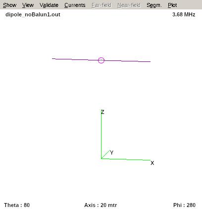
Using 4NEC2, the figure below shows an 80m dipole (only) in free-space:
Let's compute the total radiation looking end-on and rotating around the y-axis (left hand plot), and looking face-on and rotating around the x-axis:
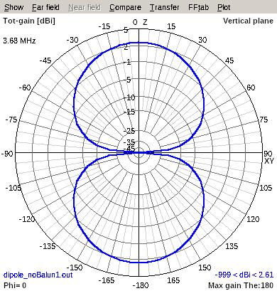
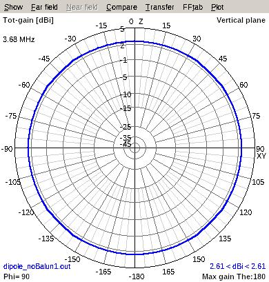
As may be deduced, we have the classic doughnut shape.
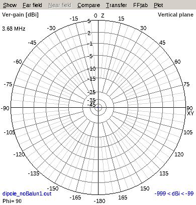
Looking face-on to the dipole, there should be no vertically polarised radiation when rotating around the x-axis. We can check this because 4NEC2 can plot just the vertically polarised radiation:
Now let's add a 1/2-wavelength wire at right angles to the dipole, whose end is at the centre of the dipole but 10cm separated from it. This might represent, for example, a balun with perfect common mode rejection. The figure below left shows that there is no current distribution on the extra wire, but move it to the right 10m and it's a different story (remember, this wire isn't connected!):
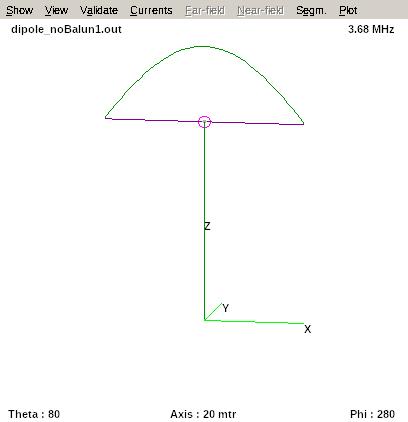
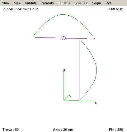
This effect may be explained by recognising that there is distributed capacitive coupling from each side of the antenna to the (disconnected) feeder. Only when the wire is in the line of symmetry does the electric field cancel - because each half of the dipole's voltage standing wave pattern are in antiphase.
Note that we could replace the suggested coax and perfect common-mode choke with balanced feeder and perfect common-mode choke and the result would be identical.
The current in the vertical wire should result in vertically polarised radiation, which we can test for (below left figure). The parasitic 1/2-wavelength wire is responsible for -1.9dBi of vertically polarised radiation. Its effect can also be seen in the total radiation pattern, where we have now lost the rejection off the ends of the dipole (below right figure).
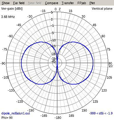
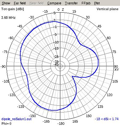
The offset position from the dipole's line of symmetry of the vertical wire was swept from zero to the end of the dipole and the vertically polarised radiation recorded. The data was plotted for a 1/2-wavelength parasitic wire and also for a 1/4-wavelength:
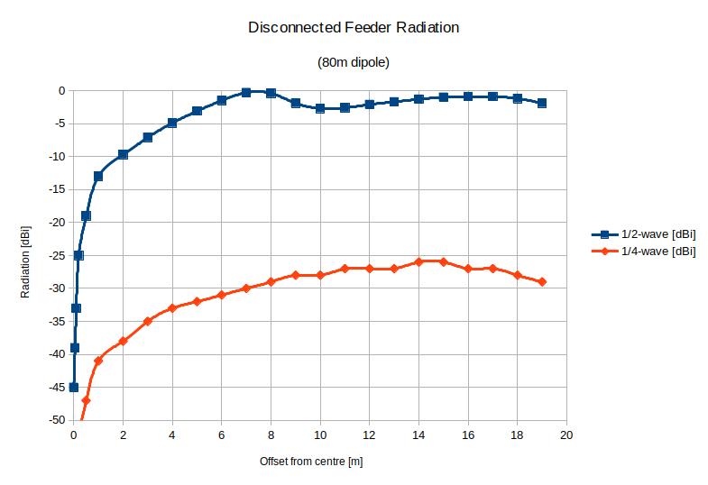
Note that even a 1/4-wavelength wire has current induced on it. In fact, any length of wire will have some current induced, but lengths close to resonance will magnify the coupling.
A Windom antenna's feedpoint would be at 19.9*2/3 = 13.3m from one end, or 19.9-13.3m = 6.6m from the centre. This is very close to the worst position for feeder radiation caused by coupling.
Even when the disconnected wire is collinear to the dipole it picks-up some energy. The figures below shows 1/2-wave and 1/4-wave wires with 10cm end separation.
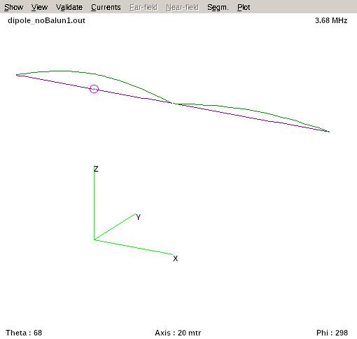
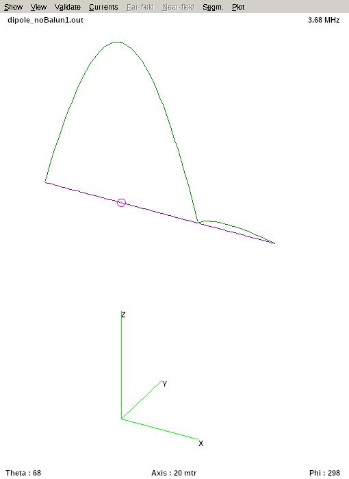
As before, the 1/4-wave fares better, but still has some current induced on it.
We must therefore conclude that Windom antennas, whether traditionally fed or ‘end connected’ will have a propensity for feeder radiation. This also applies to all types of vertical antennas, except where there is a dense enough surface of radials to encourage displacement current return via that route alone.
Conclusions
The only place a feeder can access a balanced antenna without also coupling to the antenna (and therefore radiating) is in an axis of symmetry. This is true regardless of the quality or type of balun at the feedpoint.
Otherwise, it may be possible to suppress the problem sufficiently with judicious placement of additional common-mode chokes, but it's not a good starting point. Reciprocity tells us that if noise gets onto the feeder at the shack-end it will couple onto the antenna via the same mechanism. This is the main reason why a common-mode choke on the radio mains supply can give an improvement in noise floor.


